Complete automation solution for steam curing chambers in precast concrete
The hardware and software control system for steam curing chambers was created for a plant that produces reinforced concrete products.
Task: Create a device that controls the steam curing cycle of reinforced concrete and, after the cycle is completed, activates the exhaust fan. This is necessary to release the steam outdoors, thus preventing high humidity, which negatively affects the shop’s structural elements, especially during winter.
The previously installed system worked via a Modbus interface and allowed tracking and controlling the steam curing cycle of only one workstation.
Problem with the old system:
- It only controlled one actuator in an on/off mode and couldn’t manage other devices such as the exhaust fan and the damper used to disconnect the steam chamber from the exhaust ventilation.
- Electromagnetic valves were installed on the chambers. Due to the lack of delay management between activations, they were triggered too frequently, leading to rapid failure.
- Additionally, at the time of development, the network between devices was not functioning.
Current system configuration:
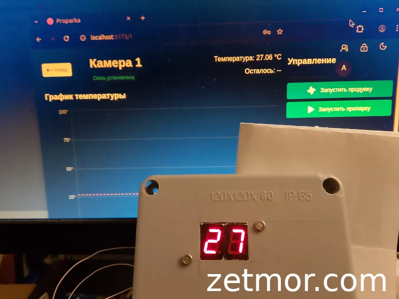
- Control controller with temperature indication
- 3-stage steam curing cycle
- Electromagnetic valve
- Type K thermocouple
- PC software for control
What is needed:
- Control of the steam valve with hysteresis and minimum intervals between activations (opening of the valve)
- Control of the exhaust fan startup upon cycle completion, with a delay setting for activation and duration of operation
- Control of the damper
- Temperature indication on the controller mounted on the chamber for visual monitoring and manual control
- Software for managing all steam curing chambers
Actuators
Steam Valve – A 220V electromechanical ball valve is used to supply steam. The valve is equipped with limit switches for status indication (open/closed). In the original design, these switches are used solely for indication and are not involved in the control logic.
Exhaust Fan – The exhaust fan motor is started using a 220V contactor.
Damper – Disconnects the chamber from the ventilation duct. The damper drive is powered by a 220V supply.
Temperature Sensor – To optimize cost and simplify the design, the thermocouple has been replaced with a DS18B20 digital temperature sensor. The maximum operating temperature in the chamber does not exceed 90°C, which is within the sensor’s operating range. Unlike the thermocouple, the DS18B20 does not require a signal amplifier for connection to an ADC and costs approximately 10 times less.
Controller and Software
Initially, a super-budget solution based on the STM32C011 controller was planned for managing the chamber actuators and exchanging data via the Modbus protocol. At this stage, firmware for the STM32C011 was developed, and the software for testing the interaction between the system elements was also started.
Initial Testing Phase
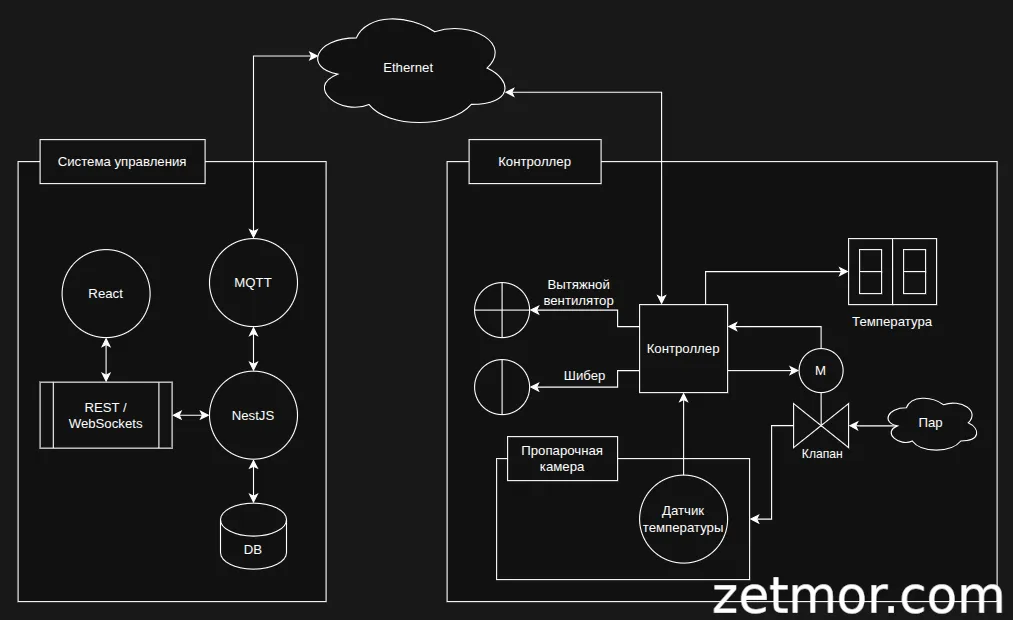
During the testing phase, it was decided to change the system topology, abandon the Modbus protocol, and switch to a more fault-tolerant architecture using standalone controllers.
Standalone controllers allow for system expansion without the need to modify physical communication lines, enable quick replacement in case of failure, have no device quantity limitations, and can be placed anywhere at any distance using wireless data transmission technologies. In addition, this solution has numerous other advantages.
The software was developed using web technologies with React for the front-end interface and NestJS for the back-end server. The data transmission protocol chosen was the lightweight and reliable Mosquitto (MQTT). This approach offers several benefits: the software can be deployed either on a local network or on remote servers, and registered users in the system will have access from any device with a web browser, whether it is a PC or a mobile phone.
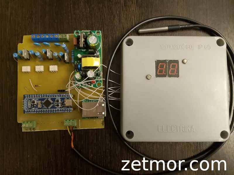
Functions of the Standalone Controller on STM32F103
The debug board includes the following functionality:
- Operation over a local network (Ethernet)
- Non-volatile memory for settings and cycle data storage, allowing recovery of data in case of connection loss, which is sent to the server once the connection is restored
- 3 control channels for actuators via a TRIAC with zero-crossing turn-on, this solution works as long as it isn’t damaged, as there’s no mechanical contact
- Connection of DS18B20 temperature sensors
- Connection of two thermocouples
- Connection of limit switches for valve position monitoring
- 1-channel TRIAC-based power controller
- Connection of a resistor to detect damper position angle
- Connection of an encoder to detect damper position angle
- Temperature indication on two 7-segment displays and a shift register, with the option to add error indication via LEDs
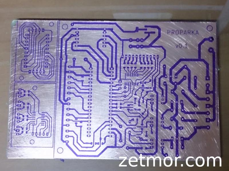
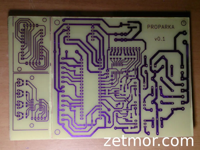
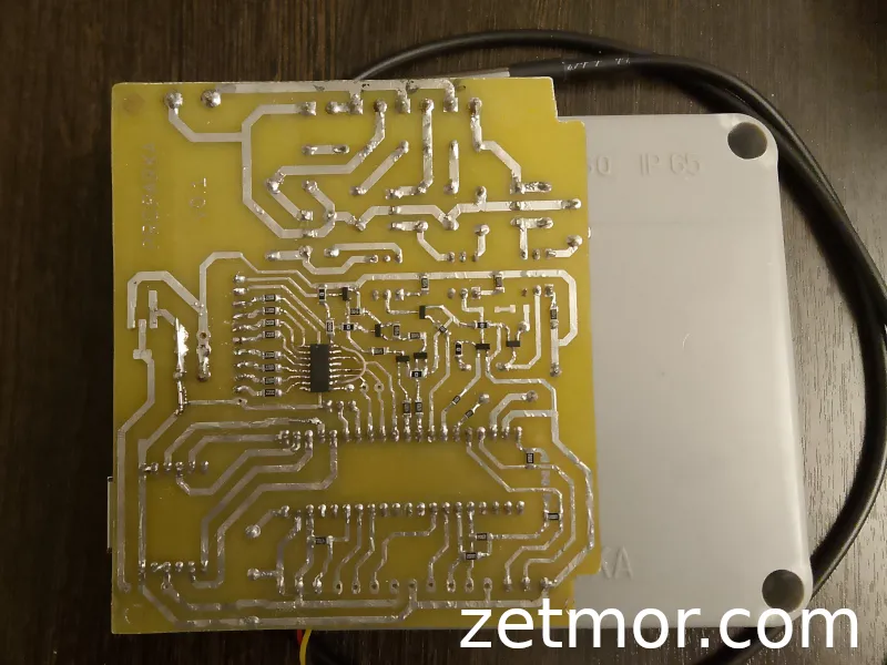
Board
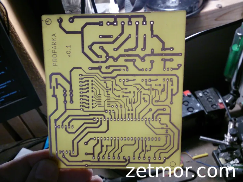
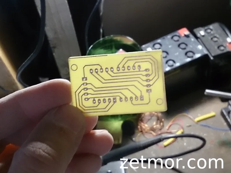
Test Device
Controller Software Features:
-
Controller Setup via UART:
- Ethernet connection settings (static IP address without DHCP support)
- MQTT broker connection settings
- Save settings to non-volatile memory
- Reset to factory defaults
- Load settings from memory upon controller startup
-
Log Output via UART
-
Automatic Reconnection to Network and Broker with exponential backoff delay
-
Dynamic Temperature Display
-
Steam Curing Cycle Start with loading all settings for the selected valve type
-
Stop Steam Curing Cycle
-
Manual Start/Stop of Chamber Purge
-
Linear Control when operating in open/close mode
-
PID Algorithm is not implemented yet (a placeholder is present in the code for future development)
-
Valve Control
-
Fan Control
-
Real-time Controller Status Update sent to the server
Software for Controller Interaction
Interfaces for both administrator and user have been implemented.
Authorization and lock screen, which activates after user inactivity.


User
- Control of the chamber (with protection against starting purge during the steam curing cycle)
- Start/Stop steam curing
- Start/Stop purge
- Automatic interface lock after user inactivity
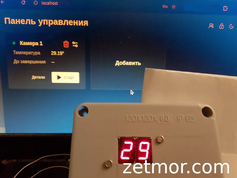
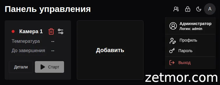
The main page displays all information about the controllers in the system:
- Controller connection status displayed as a dot:
- Green: Connection established
- Red: Connection error
- Controller state color indication:
- Red: Steam curing cycle is running, with current temperature and remaining time displayed
- Blue: Purge cycle, with delay time to start displayed, and time remaining until purge stops after it has started
- Green: Indicates that the steam curing cycle is completed

Controller Page
All information about the controller is displayed, including the current temperature, remaining runtime, and control buttons.
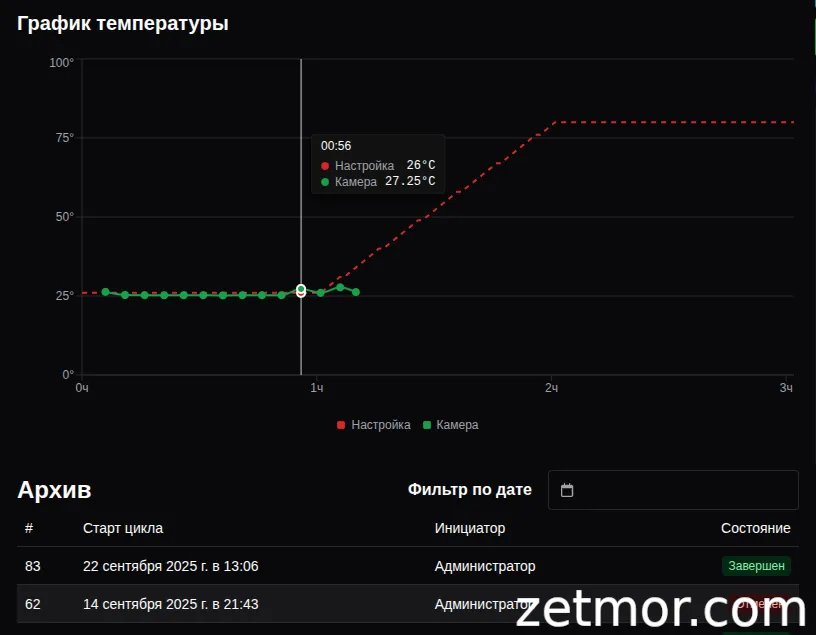
- Graph Displaying the Steam Curing Cycle:
- Red: Setup phase
- Green: Active phase, updating every 5 minutes
You can create any steam curing cycle by adding or removing stages.
- If the temperature of the previous stage is equal to the temperature of the next stage, this stage is hold—it will be shown as a horizontal line on the graph.
- If the temperature of the next stage is higher than the previous one, it is heating, and if it is lower, it is cooling.
Heating and cooling occur linearly. For example, if the temperature of the previous stage is 20°C and the next one is 80°C with a duration of 3 hours, the temperature will increase smoothly at a rate of 20°C per hour.
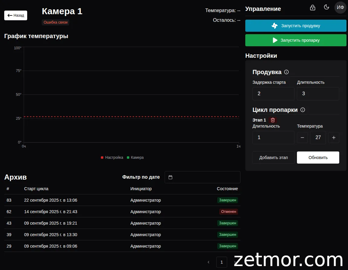
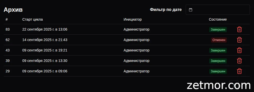
System Archive
The system maintains an archive that contains complete information about steam curing cycles, including the state and initiator of each cycle.
When selecting a specific cycle from the archive, all related information is loaded, and graphs of both the set cycle and the actual working cycle of the steam curing process are displayed.
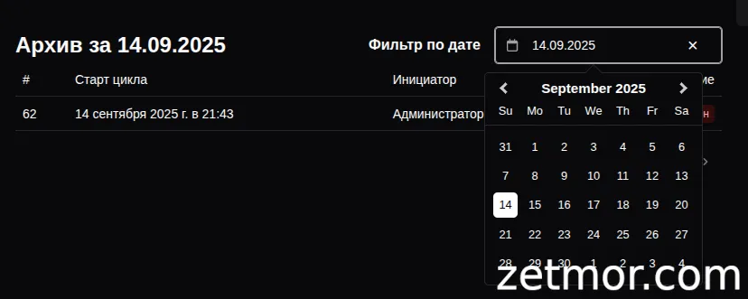
The archive includes a date-based search feature, allowing users to quickly find cycles based on specific dates.
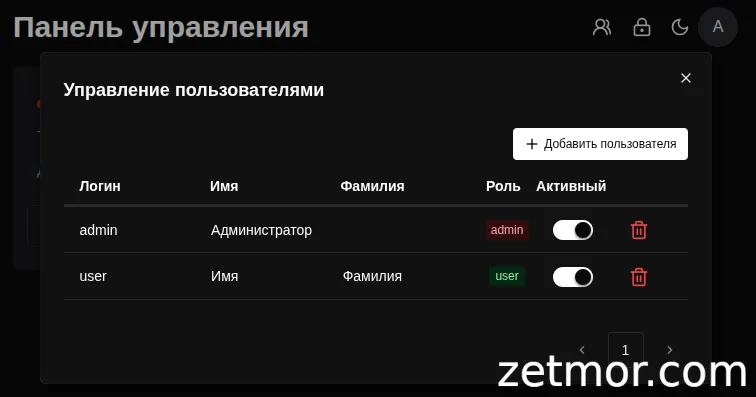
Administrator
The administrator has access to all user functions, along with additional capabilities:
- User management
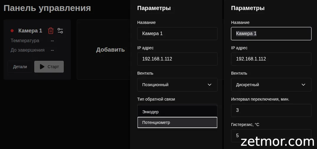
- Adding controllers to the system, with basic settings for the selected valve control type
- Deleting data from the steam curing cycle archive
Smart Control for Steam Curing Chambers — A Technology That Works for You!
Imagine — your products gain strength faster, the process runs strictly on schedule, and you save time and energy while overseeing the flawless operation of the system!
You can order the hardware-software complex for steam curing chamber control — and transform the production of precast concrete into a smart, reliable, and profitable process, where every minute works towards quality and results.
And if needed, we’ll expand the functionality to fit your specific needs, ensuring the system perfectly integrates into your technology and helps achieve maximum efficiency.