DIY CNC Milling Machine
As a hardware enthusiast, I have long dreamed of making a CNC machine (computer numerical control). I nurtured this idea for 3 years. But dreams are meant to come true, so I began turning mine into reality. After reading countless forums and reviewing a huge number of hobbyist and professional machines, I decided to build a budget prototype entirely with my own hands — from the machine frame to the control electronics.
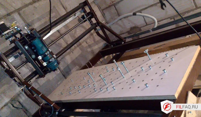
First, I decided on the working area of the machine and the linear motion components — whether it would be ball screws (ball screw drive), a spindle with metric or trapezoidal thread, or a rack and pinion. This choice influences the material for the frame, the motor power, and the electronics. Of course, a larger working area is desirable, but the bigger the area, the more expensive the machine. Therefore, I settled on a working area of 800x800x200 mm, which allows machining quite large parts made from soft materials such as wood, plastics, and the like.
Now, let’s move on to the construction description
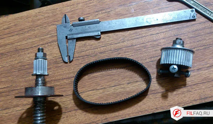
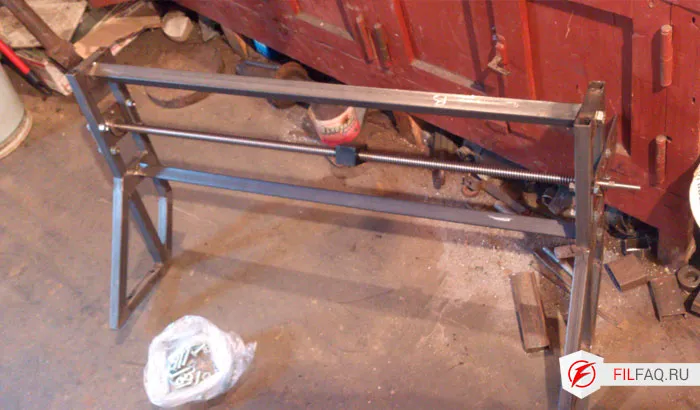
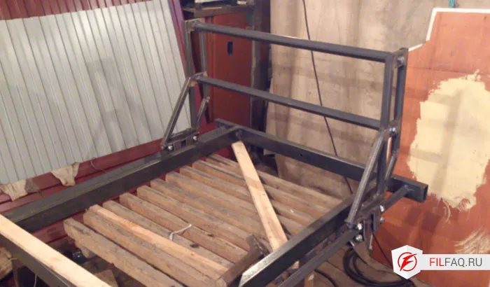
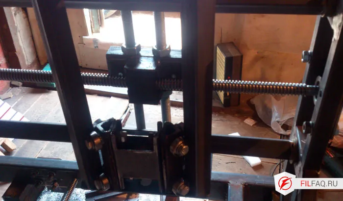
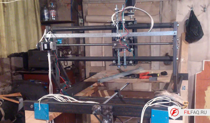
The construction consists of welded frames stacked on top of each other, using ball bearings that allow individual parts of the machine to move, thus changing the position of the cutting tool along the XYZ axes. This design is low-cost because the linear motion system is assembled from the same square tubes. A set of tubes for my machine cost about 2000 rubles. Next, I chose how to move the machine’s frames (the gantry): trapezoidal screws with a 5mm pitch plus polyamide nuts.
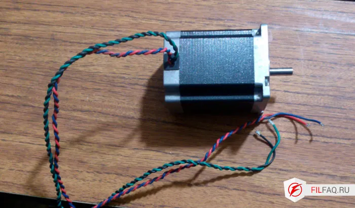
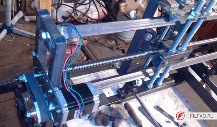
Stepper motors Nema 23 with belt drives (taken from an electric planer) are used to drive the lead screws.
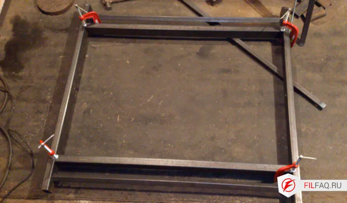
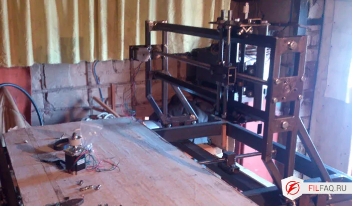
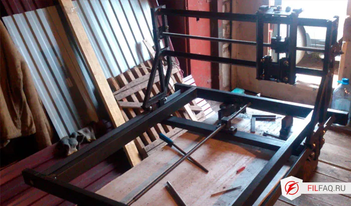
Construction process
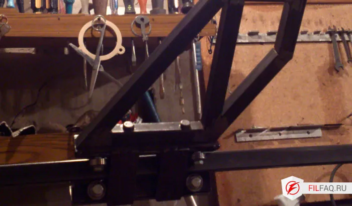
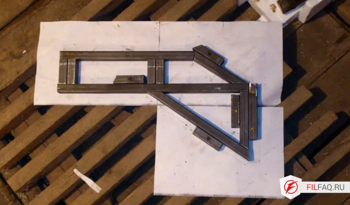
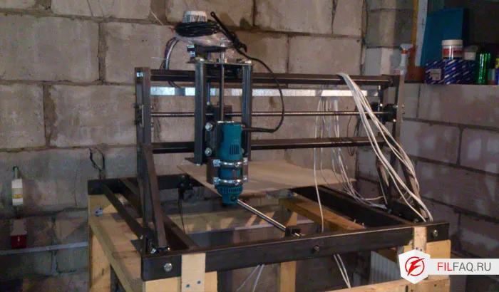
The machine bed (X-axis) is made from rectangular tubing 30×60×2 mm, the gantry supports (Y-axis) from 20×20×2 mm tubing, and the guides from 25×25×2 mm tubing. The Z-axis is as compact as possible, made from available scrap metal — specifically, two pieces of square tubing and a garage surface-mounted lock :)
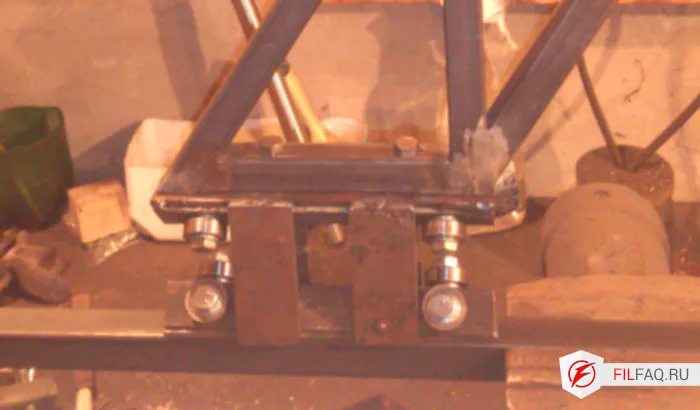
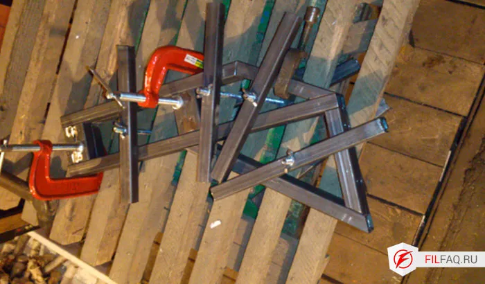
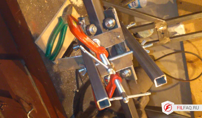
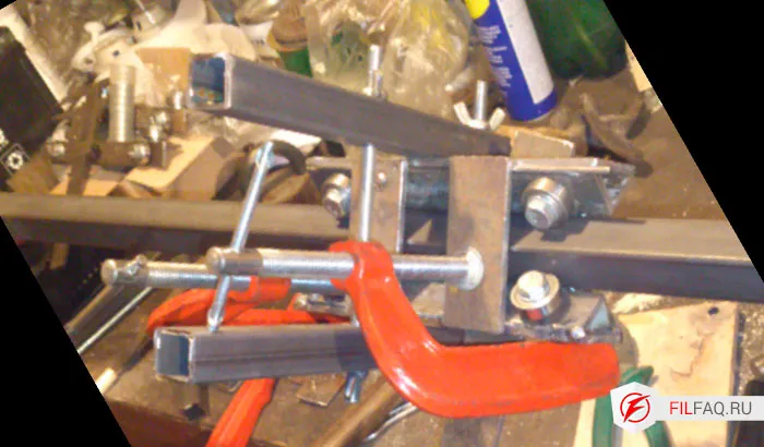
To allow all parts to move relative to each other, I made carriages. A carriage consists of two angle brackets with eight bearings. All components have adjustable clearances, which inevitably appear during operation.
Electronics
So, we have Nema23 57H76-D6 motors: 57×76 mm, torque 18.6 kg·cm, shaft diameter 6.35 mm, current 2.6 A, step angle 1.8°, inductance 4.5 mH.
Let’s calculate the maximum voltage for the given motor inductance. To determine the maximum voltage you should use based on the stepper motor’s coil inductance, use this formula:
Maximum voltage = 32 × √(Inductance) (where √ is the square root) 32 × √4.5 = 67.9 V maximum.
I purchased a NES-350-48 switching power supply with 48 V and 7.3 A capacity to power three motors. Next, drivers are needed to control the motors.
Author's description for setting up the stepper driver circuit
Stepper driver PCB layout in SprintLayout 5.0
Long ago, when assembling these drivers, there was a problem with incorrect IR2104 chips. Below is the tester.
Tester PCB layout in SprintLayout 5.0
For convenient connection and protection of the computer’s parallel port, I assembled an optocoupler isolation board. The interface board allows controlling four any motor controllers for CNC machines with support for STEP, DIR, ENABLE signals, two power elements of the machine, has a high-speed output for spindle speed control (PWM), and supports connection of various sensors (LIMIT, HOME, E-STOP) in needed combinations (5 inputs).
When writing the control program, note that the ENABLE signal is common to all four channels. Using the values specified in the schematic and careful assembly, the circuit requires no additional tuning.
Optocoupler isolation PCB layout in SprintLayout 5.0
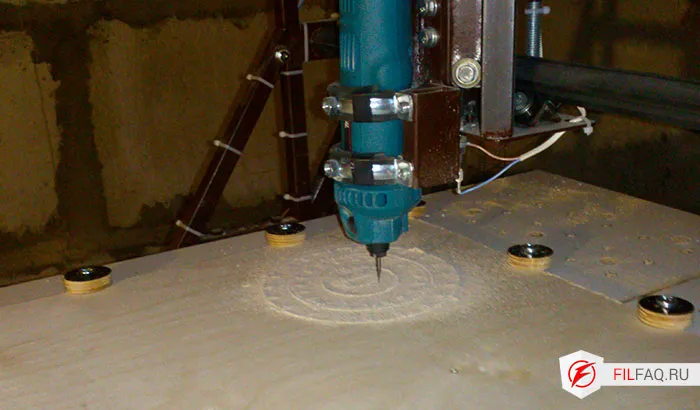
Photos taken during the building process
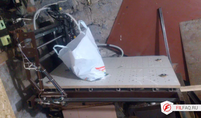
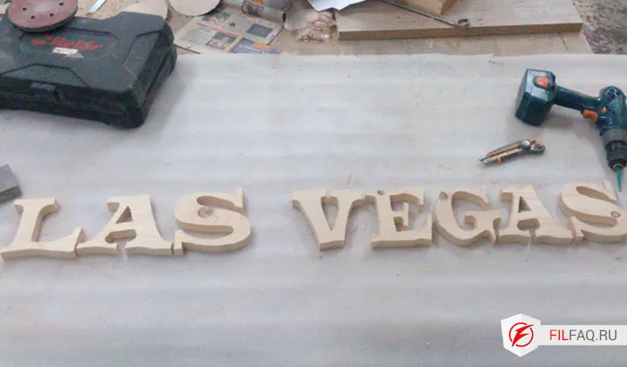
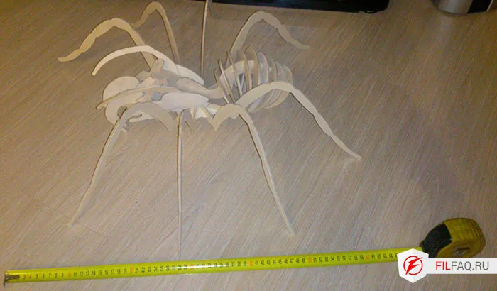
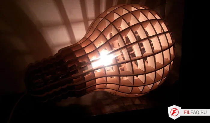
Photos of what was being manufactured on the machine