DIY CNC Machine + Blueprint
A machine that anyone can build!
There are not many ready-made projects online for building a CNC machine on your own.
- Therefore, I took a machine I found on Avito (a Russian classifieds site) and based on its photos, quickly “designed” or rather just drew a machine.
- My project will help those who want to assemble a CNC milling machine with their own hands.
- The reasons may vary: you may not have money for a ready-made one, or you might just want to build something yourself.
In any case, this article is for you.
The idea for writing this article came from another statement by a “manufacturer.”
Some “experts” sell CNC machines and their components cheaply, trying, as it seems to me, to make money from the ignorance of those eager to get such a magical machine for their woodworking needs. I’m talking about CNC milling machines for wood because, in my opinion, they are unsuitable for commercial use due to the time it takes to process a product. Most people need such a machine for commercial purposes.
If you have a lot of time, this article will help save money if you decide to assemble such a machine.
In this article, you will get complete information on the mechanics of a three-axis gantry machine, including blueprints and files to send for manufacturing or for making the machine’s components yourself.
Difficulties and Challenges
The main difficulty is selecting the right components to match the desired working area of the machine. Everything is made using ready-made parts from AliExpress. Essentially, you’re getting a ready-made construction kit, so assembly shouldn’t be a problem.
Plan of Action for Assembling the Milling Machine
1. Determining the Machine’s Dimensions
- The size of the working area depends on the lead screws.
- Lead screws with standard thread ends are sold in sets on AliExpress.
- The kit includes: lead screw, nut, nut mount, coupling, and lead screw holders.
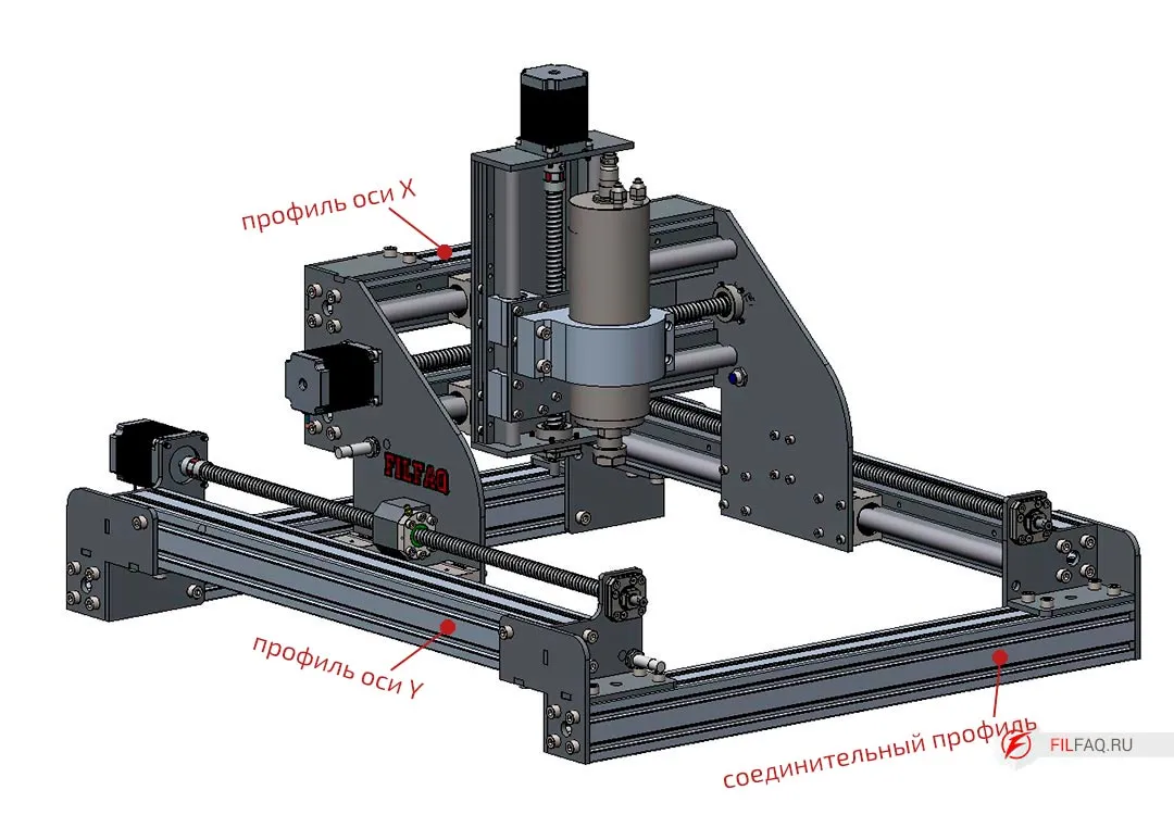
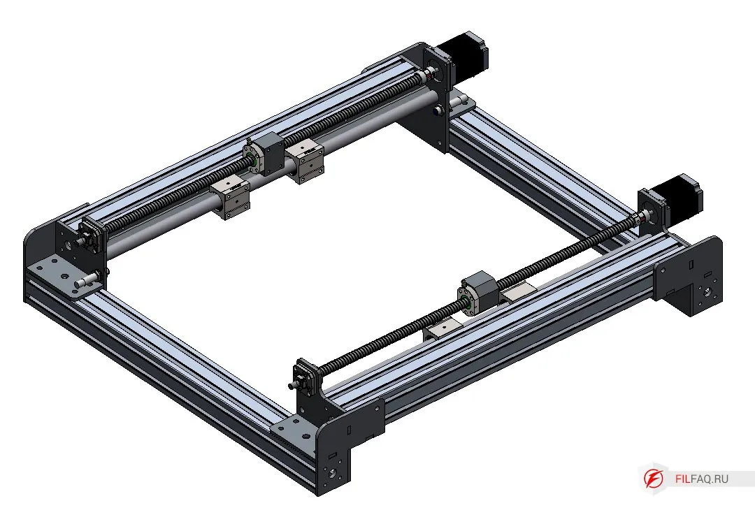
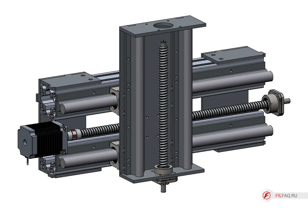
This machine has the following dimensions:
- Y-axis: screw 700mm, profile 685mm
- Connector profile 685mm
- X-axis: screw 470mm, profile 455mm
- Z-axis: screw 300mm
With these parameters:
- Working area: X-295mm, Y-480mm, Z-160mm (dimensions without limit switches installed).
Example To increase the Y-axis size, take a 1500mm screw, and the profile length will be 1485mm (1500-700+685=1485). Increase the X-axis (gantry). For a 1200mm screw, a profile length of 1185mm will be required (1200-470+455=1185). The connector profile length will be 1385mm (685+(1200-500)=1385). With these screws, we get a machine with a working area of X-995mm, Y-1280mm, Z-160mm.
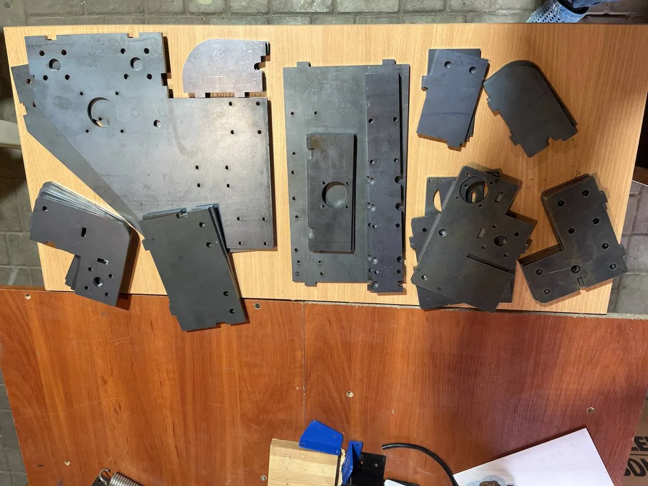
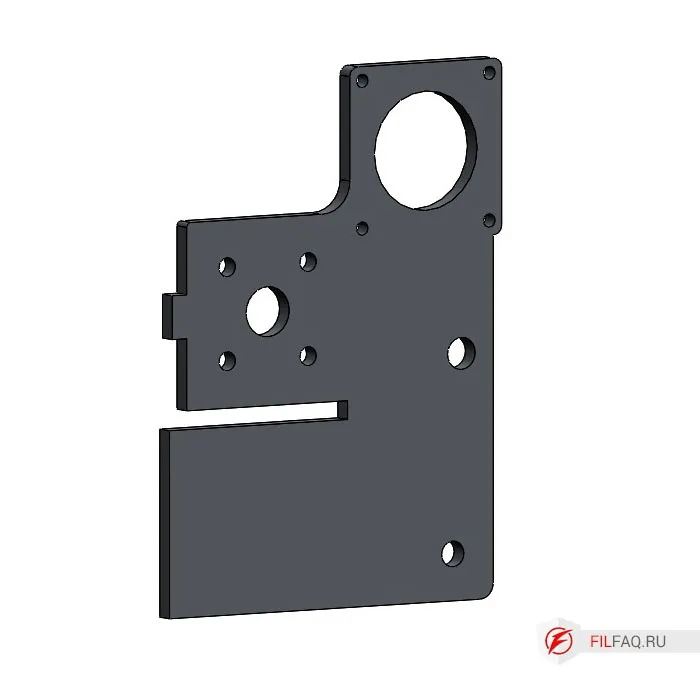
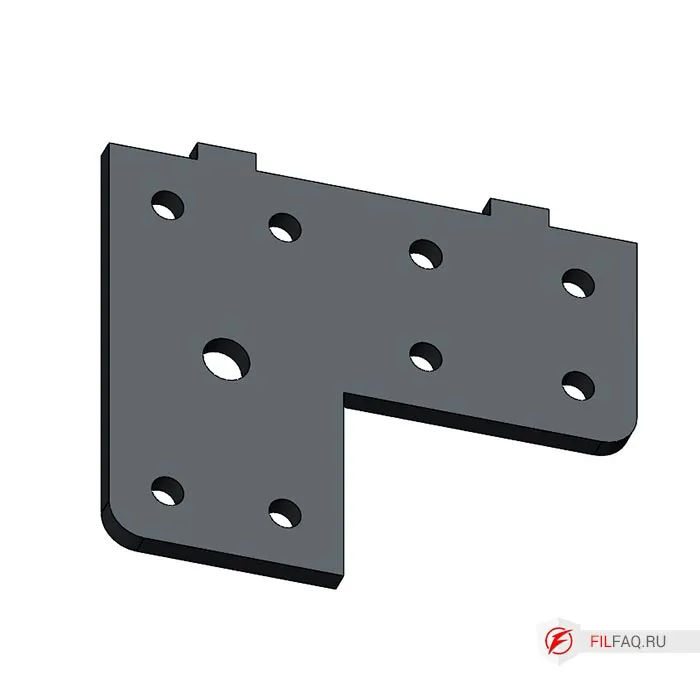
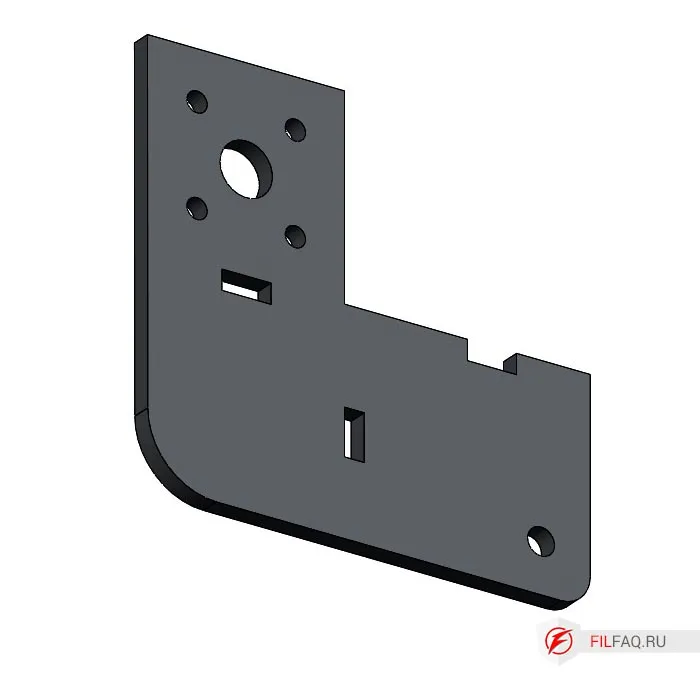
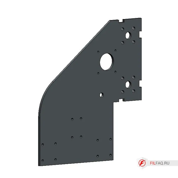
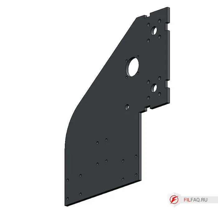
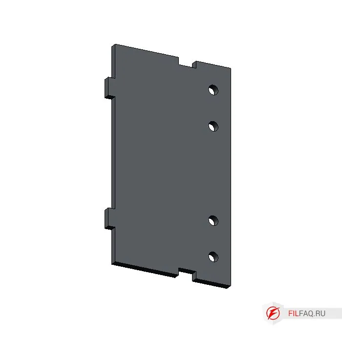
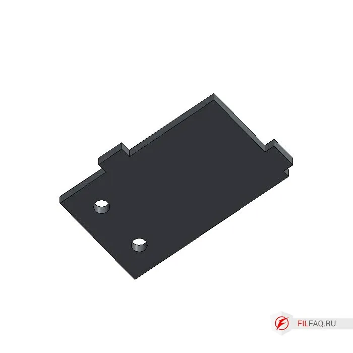
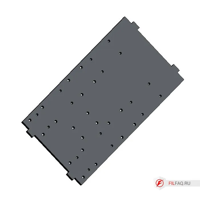
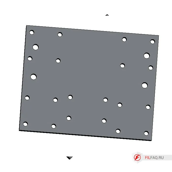
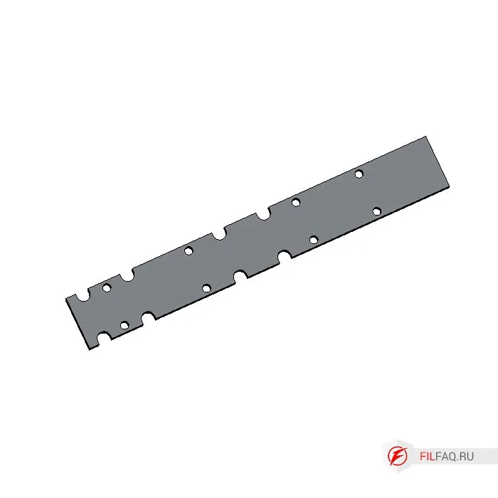
2. Metal Parts
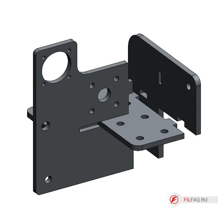
- The machine consists of 14 different parts made from 6mm structural steel St3. The parts are welded together, and positioning is done using a tongue-and-groove system, which easily assembles the elements into one piece.
- By clicking on the image in the description, you can see the number and quantity of parts needed to assemble the machine.
- I recommend ordering the parts for laser cutting. For small holes, use a center punch before drilling and threading.
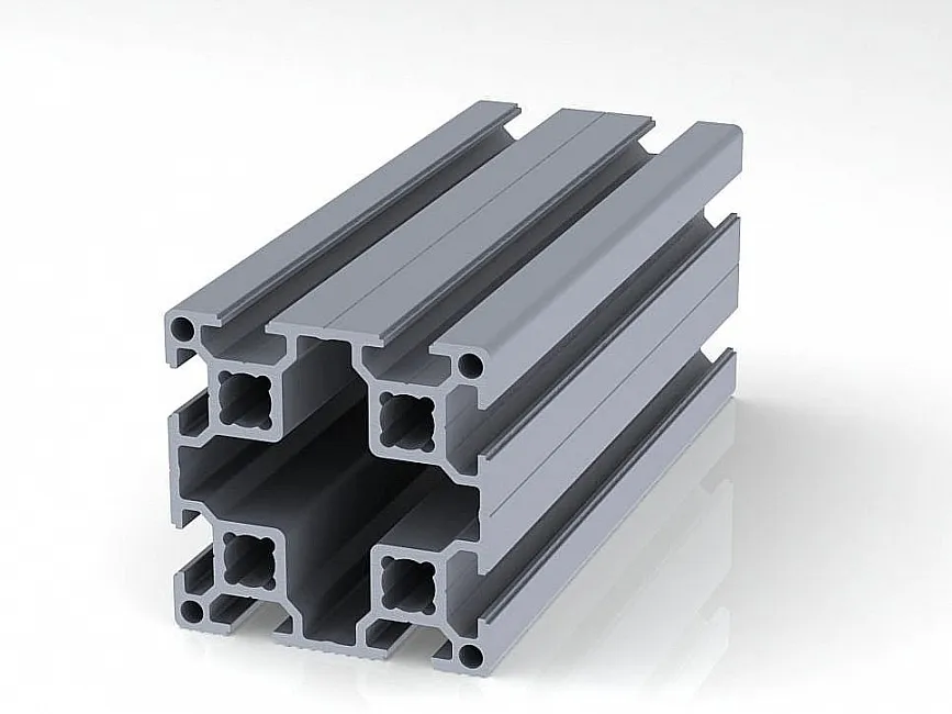
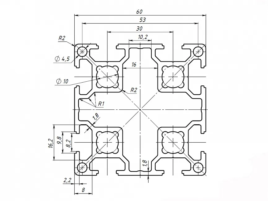
3. Aluminum Profile
- Aluminum profile 60x60, series 30, cut to size depending on the length of the selected lead screw.
- Choose the length of the screw and calculate the profile length for each axis. I explained how to calculate it earlier.
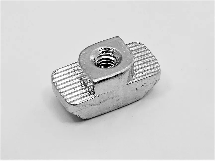
- T-nuts are used to connect the welded parts to the profile.
- Screws M5, M6, M8, M10.
4. Components from AliExpress
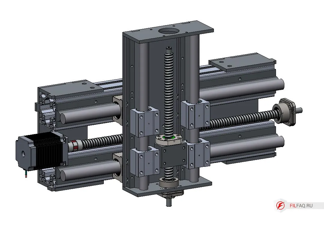
For the mechanics, the following components are required:
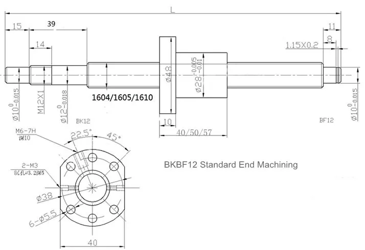
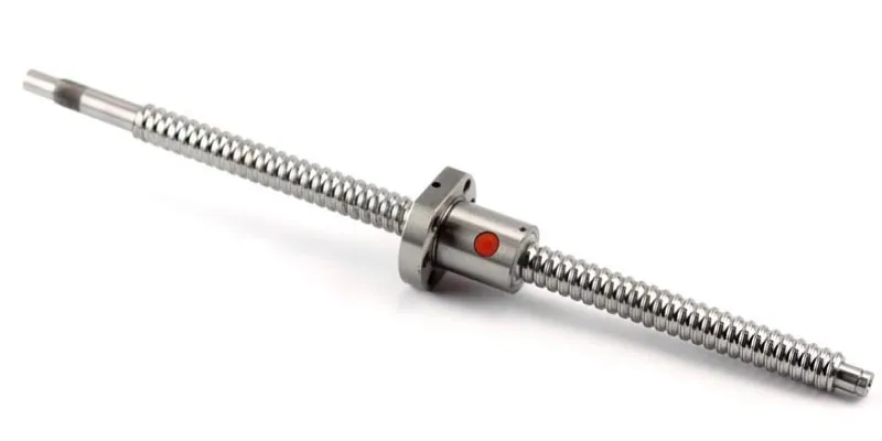
- Four 1605 screws (ball screw) of different lengths (X, Y, Z axes)
- Four 1605 nuts
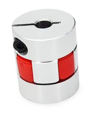
- Four couplings with diameters of 10mm and 8mm
- Four nut holders
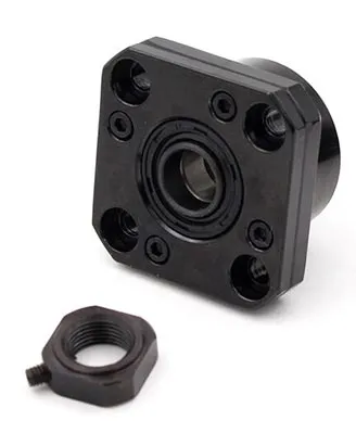
- Four fixed supports FK12
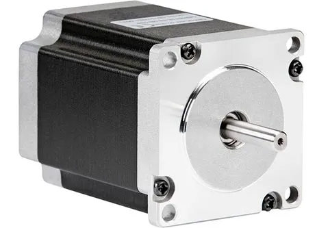
- Four NEMA23 stepper motors with 18kgf holding torque
- Cylindrical rails SBR20 for the X and Y axes, SBR16 for the Z axis
- SBR20UU bearings for X, Y (8 pieces), SBR16UU for Z (4 pieces)
Ball screw (ШВП) 1605 refers to a ball screw with a 16mm diameter and a 5mm pitch per revolution.
- The profile can also be viewed on AliExpress.
5. Assembly of Parts
- First, cut threads in all parts according to the drawings.
- The assembly of parts is done using a tongue-and-groove method; after assembly and fixation, weld them.
- Weld carefully—avoid overdoing it, or it may warp and everything will be crooked.
- Tack weld or weld the tongue-and-groove joint, or combine both methods.
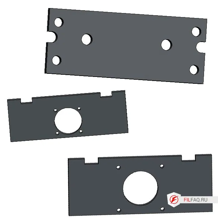
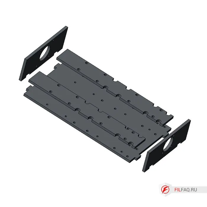
5.1. Assembling the “corners” of the main frame of the CNC machine
To assemble, use parts 1, 2, 3, 4 to create the corner elements of the CNC machine frame, as shown in the drawing.
Pre-cut the threads according to the drawing.
Note that the “corners” are assembled mirrored.
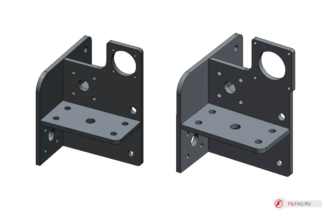
Now we have 4 “corner” elements.
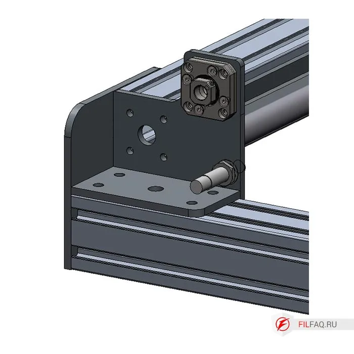
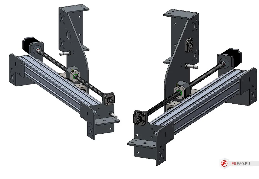
5.2. Assembling the Portal Stand
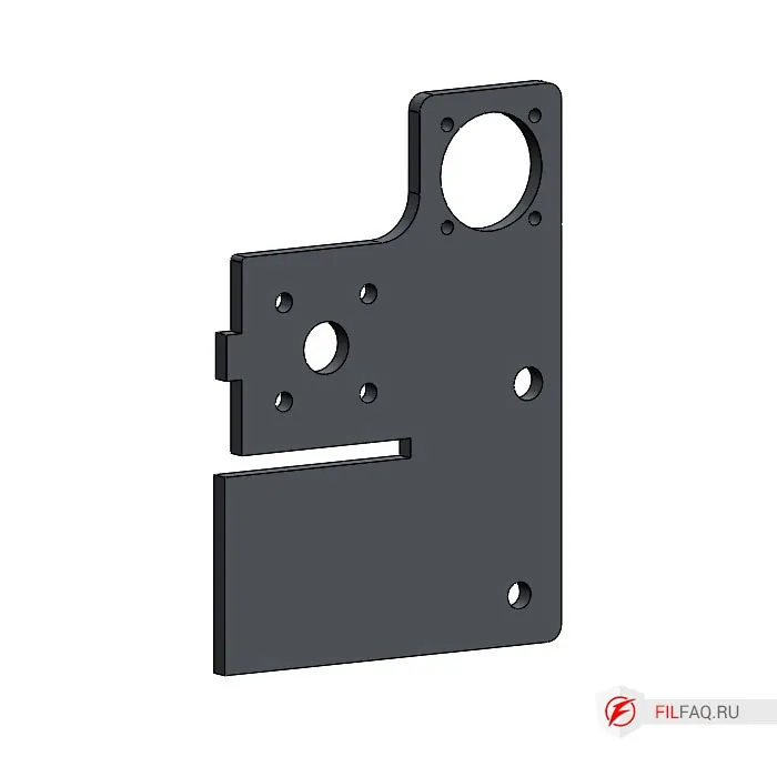
The portal stands for the CNC machine are assembled in a similar manner to the corner elements. Take parts 5, 6, 7, 8 and carefully assemble them. Make sure you install the small parts correctly. Part 5 will hold the motor that drives the carriage along the axis.
Pre-cut the threads according to the drawing.
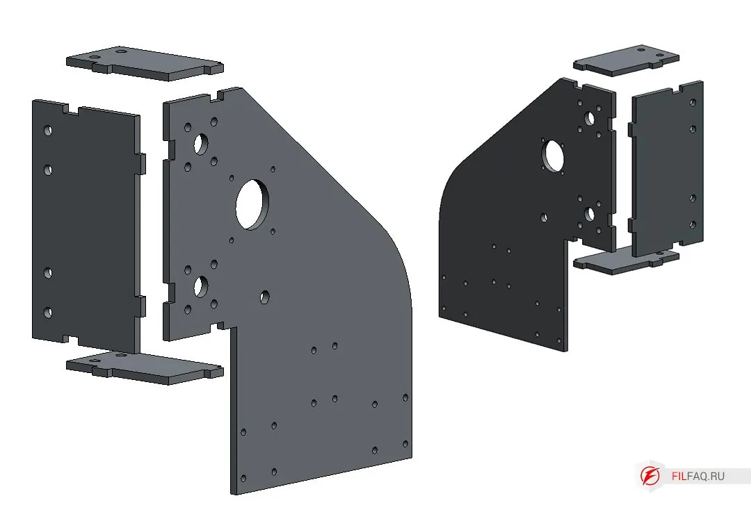
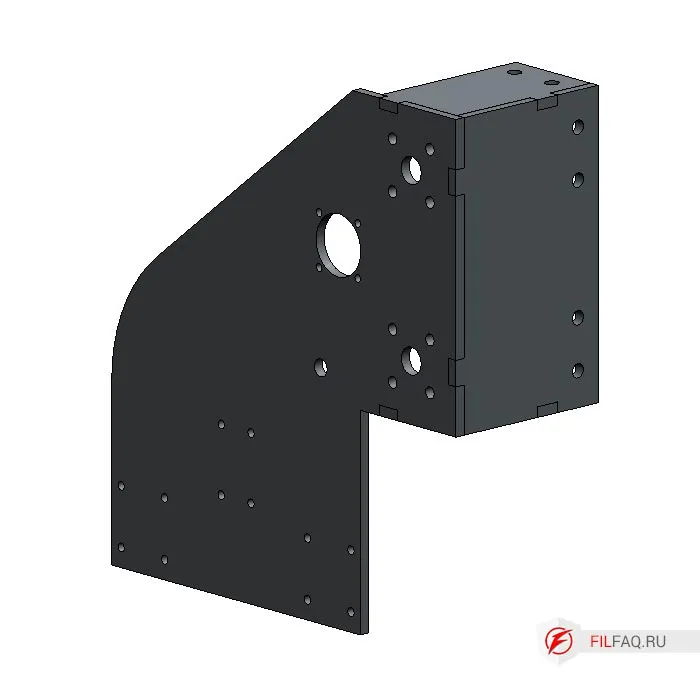
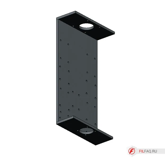
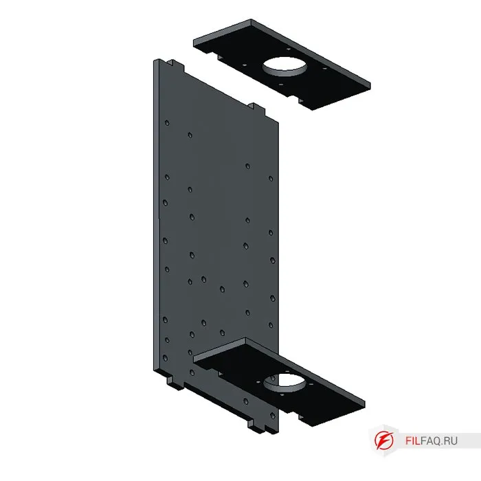
5.3. Assembling the Z-Axis of the CNC Machine
The base of the Z-axis is assembled from parts 9, 12, 13. Follow the image closely and assemble carefully without mixing up the parts.
Pre-cut the threads according to the drawing.
Fix the parts to be welded. For example, you can use a square tube and clamp the parts with clamps to achieve a 90-degree angle. Even if the angle is not perfect, the coupling between the motor shaft and the ball screw (ШВП) has a soft insert that compensates for any misalignment.
6. Assembling the CNC Machine
Now that all the parts are ready, it’s time to assemble and screw everything together to create the machine. Later, the CNC system can be installed, such as MACH 3, 4, or LinuxCNC.
The aluminum profile is assembled using T-nuts, so you’ll need a handful of nuts and screws. I use screws with an internal hexagon (DIN 912), and I recommend using grade 8.8 screws, which are available at any hardware store.
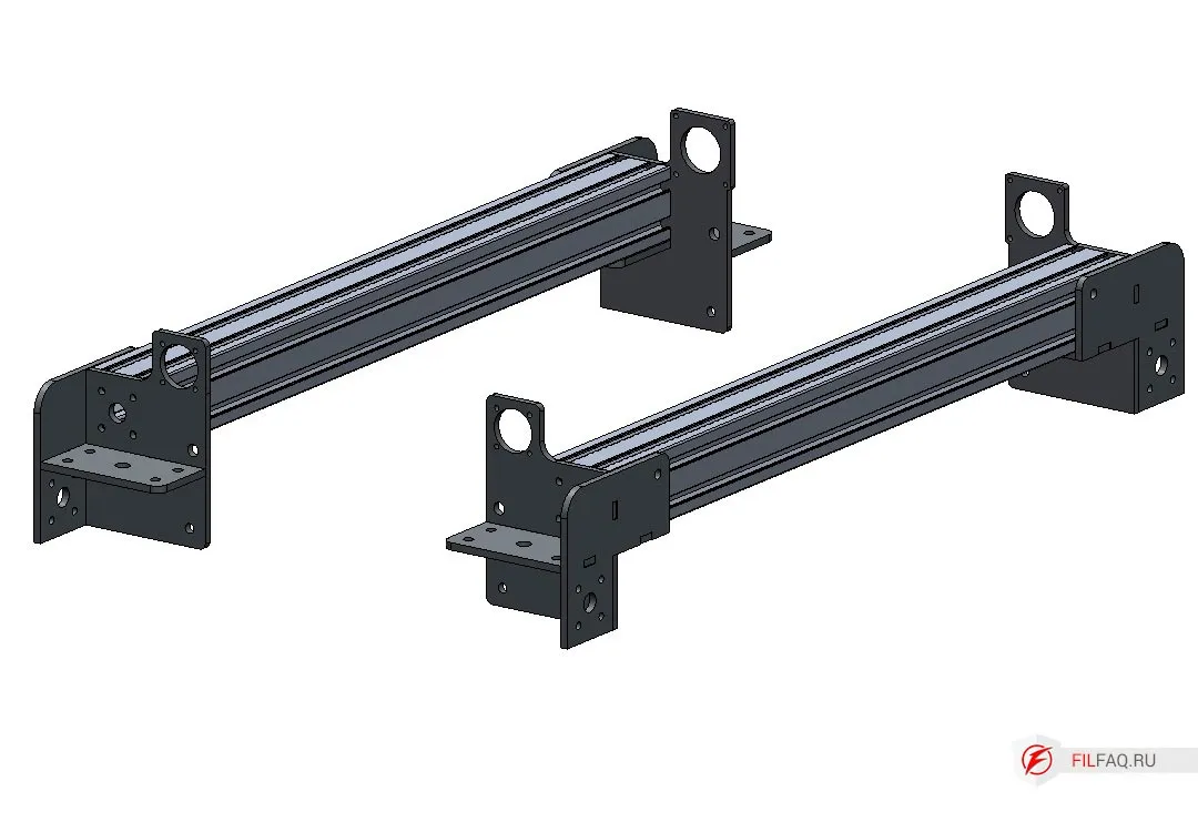
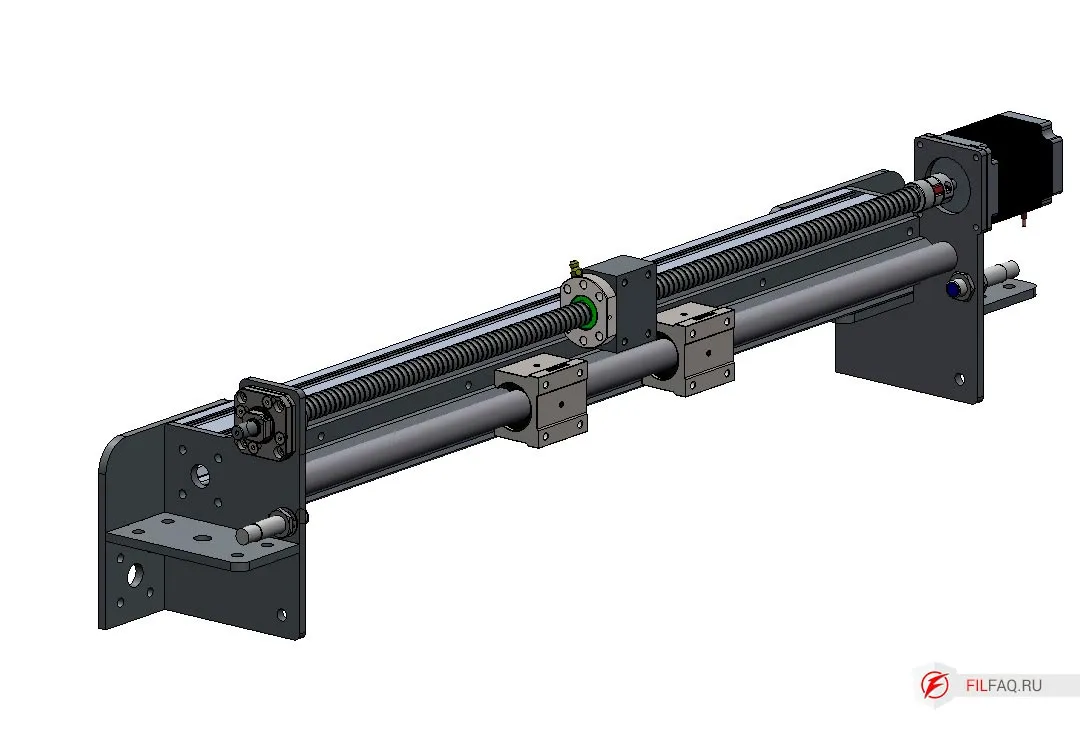
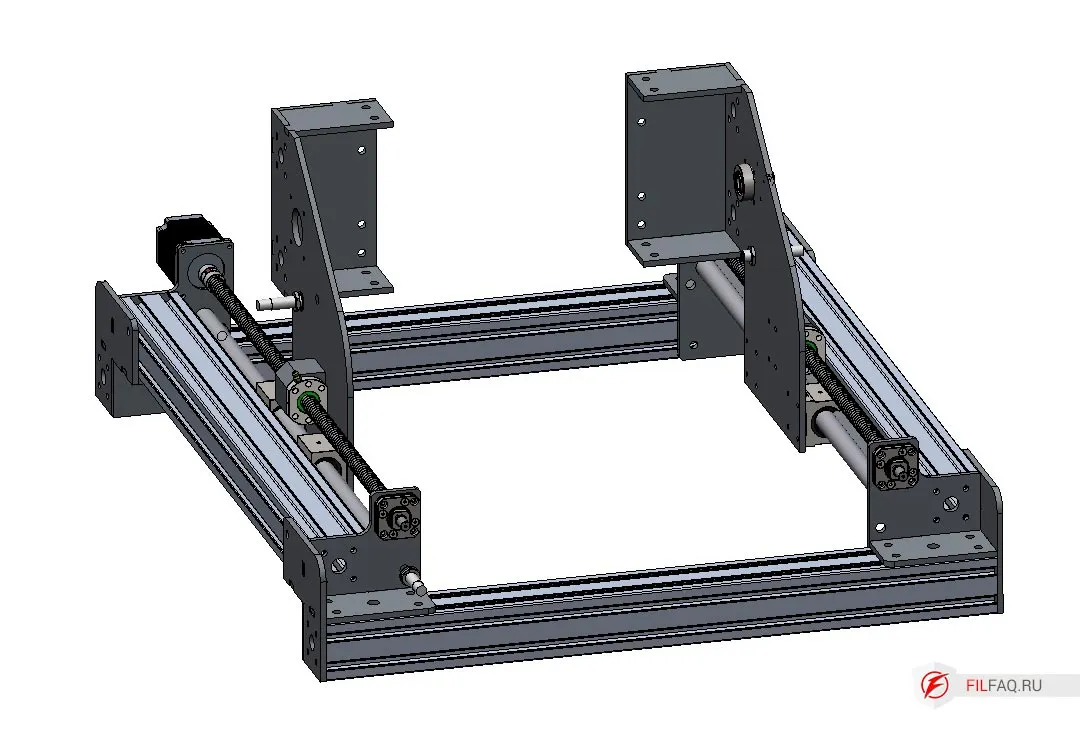
6.1. Assembling the Left and Right Y-Axis
- Install the corner elements.
- Assemble the guide rail. Mount two SBR20UU carriages onto the cylindrical SBR20 rail and secure it to the 60x60 aluminum profile using M6 screws.
- Repeat the same process for the second guide rail.
- Use M8 screws to connect the two rails to the prepared profile, which will set the length of the X-axis. Do not tighten yet.
- Install the FK12 fixed nut holders into the corner elements, securing them with M5 screws.
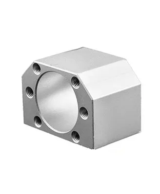
- Take a screw with a nut already attached, fit the nut holder to the stand, and secure it with six M5 screws.
- Install the 1605 ball screw into the FK12 support with its threaded end, slightly tightening the nut on the support.
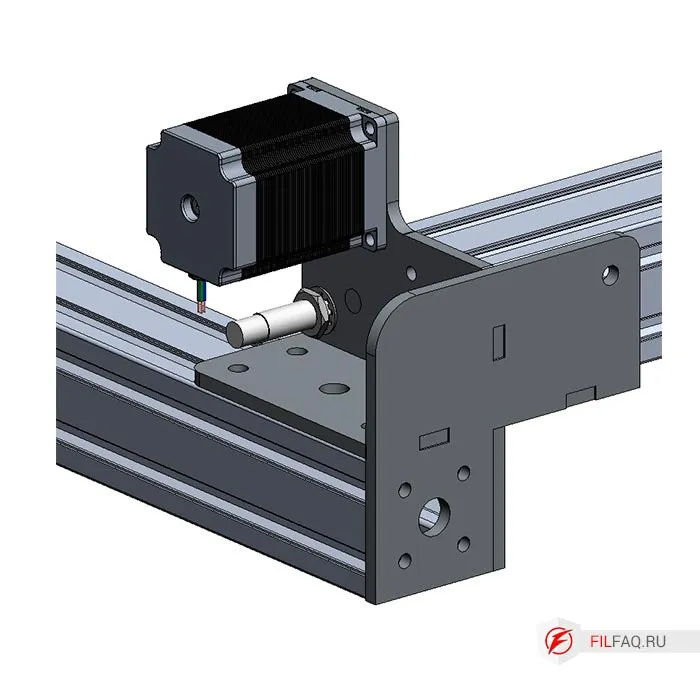
- Mount the NEMA 23 stepper motor with the coupling on its shaft in its position. Secure it with M5 screws. See the diagram.
- Tighten the nut that secures the ball screw to the FK12 support and fix the coupling on the ball screw and motor shaft by tightening the screws on the coupling halves.
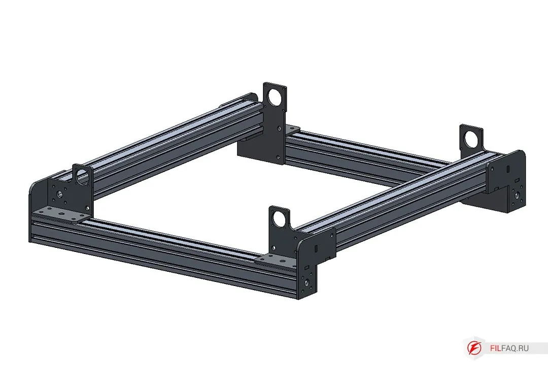
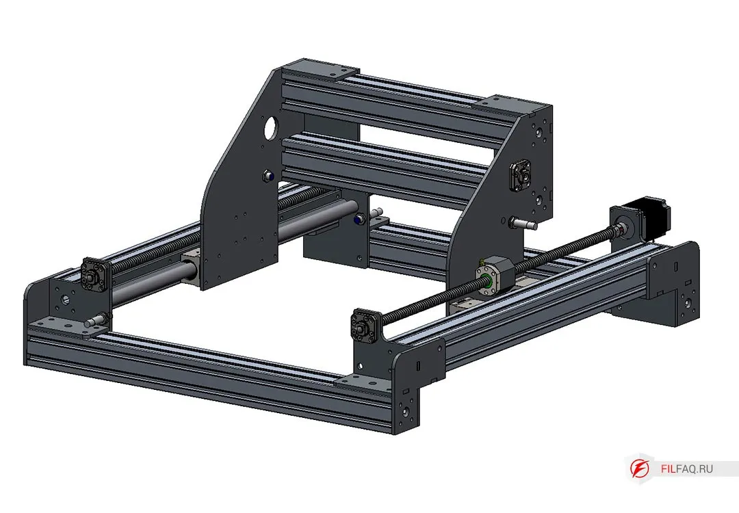
6.2. Portal of the Milling Machine, X-Axis
- Attach the portal stand to the SBR20UU bearings using M5 screws. Do not attach the SFU1605 ball nut to the stand yet.
- Install the pre-prepared portal profile and secure it with M8 screws. Do not tighten yet.
- Slide the portal to one side until it hits the stopper, then tighten the M8 screws of the main machine frame.
- Slide the portal to the opposite side and tighten the main frame screws again.
- Check how smoothly the portal moves by sliding it back and forth. Make sure it moves smoothly along the entire Y-axis length. After this, tighten the main machine frame screws.
- Assemble the X-axis guide rail by mounting two SBR20UU carriages onto the SBR20 cylindrical rail, securing it to the 60x60 aluminum profile with M6 screws.
- Install the FK12 nut support on the right side of the portal and secure it with M5 screws.
- Mount the ball screw, attach the nut, and install the coupling holder, securing it with six M5 screws.
- Install the 1605 ball screw into the FK12 support with its threaded end, slightly tightening the nut on the support.
- Mount the NEMA 23 stepper motor with the coupling on its shaft in its position. Secure it with M5 screws. See the diagram.
- Tighten the nut that secures the ball screw to the FK12 support and fix the coupling on the ball screw (do not fix it on the motor shaft).
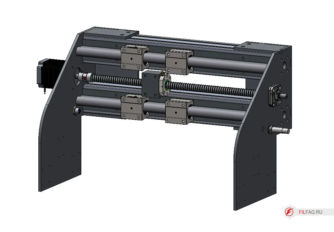
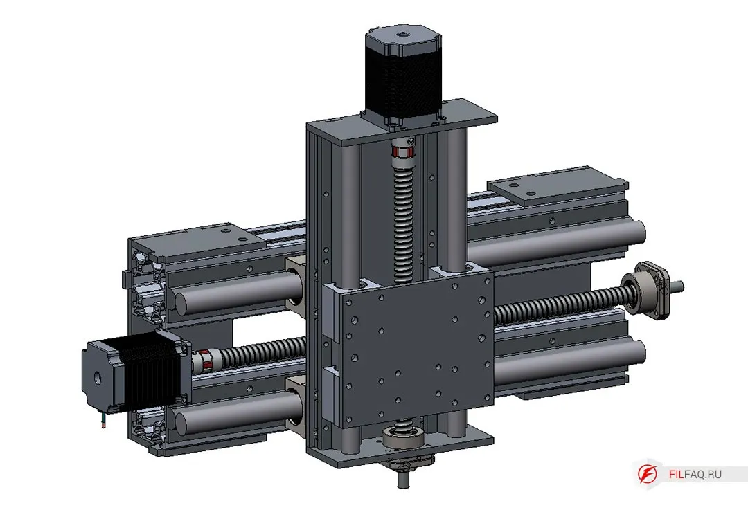
6.3. Z-Axis of the CNC Milling Machine
- Install the FK12 support at the bottom of the Z-axis platform and secure it with M5 screws.
- Install the Z-axis base on the SBR20UU bearings, securing it with M5 screws. Tighten the screws.
- Slide the base to the left and tighten the profile mounting screws to the stand. Slide it to the right and tighten the right stand screws.
- Adjust the movement for smooth X-axis operation, then tighten the profile screws to the stands.
- Slide the SBR16UU bearings onto the SBR16 cylindrical rails and secure them with spacers Part 14 to the Z-axis base using M5 screws.
- Attach Part 10 to the SBR16UU bearings and tighten the screws.
- Move the Z-axis carriage to ensure smooth motion, then fix the screws securing the cylindrical rail and Part 10.
- Install the ball screw with the nut and nut holder to the moving spindle bracket. Secure the nut with a screw.
- Mount the motor with the coupling.
- Install the spindle bracket. In this configuration, a spindle bracket spacer is used.

And that’s it! The complete DIY CNC machine assembly that anyone can tackle.
All that’s needed is some welding and threading, maybe some trimming of the cylindrical rails.
- Don’t forget to tighten all the screws.
- If necessary, install limit switches and flexible cable channels.
- If you’re feeling lazy to thread the holes, use screws and nuts.
What Can Be Improved
- Add brackets for the flexible cable channel.
- Increase rigidity, for example, by adding crossbars or creating a “sacrificial” table made of 18mm plywood.
- Refine the portal stands and Z-axis design to make the entire structure lighter.
Conclusion
Anyone Can Build This Machine
I’ve tried to explain in detail how and from what materials you can assemble this CNC machine.
- The size of the machine is up to you, but don’t make it too long with this design.
- This type of machine is a great way to get familiar with material processing through cutting. You’ll discover the machine’s operating modes, how long it takes to make a part, a 3D model, and so on.
Later, you will be able to draw conclusions based on your own experience (as I did after assembling my second machine) first here, and you’ll better understand what you want from your CNC milling machine. You’ll also realize the limitations of super-budget machines.
And you won’t fall for all the tricks, such as, “We can install this spindle, or we can upgrade to one five times more powerful.” But no one ever asks, what are you planning to cut with it? A powerful spindle on a weak machine can’t reach its full potential. And that applies to all the machine’s components. (This is especially true for cheap, semi-homemade machines that are everywhere.)
A machine is a mechanical system, and it’s quite complex when it comes to load-bearing. A lot of work is needed to ensure that it works properly.
Everything in this article is my own opinion based on my personal experience in building, maintaining, and upgrading my machines, as well as dealing with machines from those so-called “super-duper” manufacturers.
I’m not a super expert in this field, and I don’t have any academic degrees, but I do have 5 years of experience working with my two self-built CNC machines.
Good luck to those who want to build their own CNC machine!
Download DFXThe plans are provided as-is, so make sure to double-check everything before you start working.
CNC Machine Built Using My Plans
In this version, the aluminum profile was replaced with steel.