Second homemade CNC milling machine
3x2m CNC milling machine made by hand, plans, ideas, desires.
After I assembled and successfully launched my first CNC router, the real magic began.
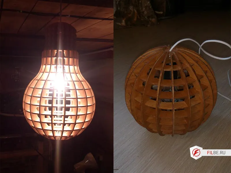
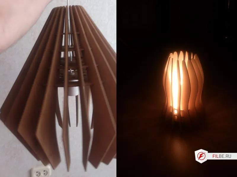
From simple plywood sheets, I created cozy lamps, delicate patterns, letters for signs, and sometimes — even small pieces of furniture.
The local hardware store was happy to accept my creations.


But the more I got into it, the clearer I realized: you won’t get rich with such a machine. It was more of an inspiring hobby, bringing immense joy, but consuming a lot of time.
Yet, this experience turned out to be priceless: it was then that I understood what my ideal machine should be — powerful, precise, and versatile.
Inspired by this, I began designing a new CNC machine, based on the available metalworking capabilities in my region.
CNC Machine Concept
After sifting through a ton of information and calling dozens of metalworking companies, I decided:
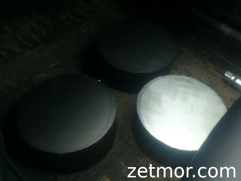
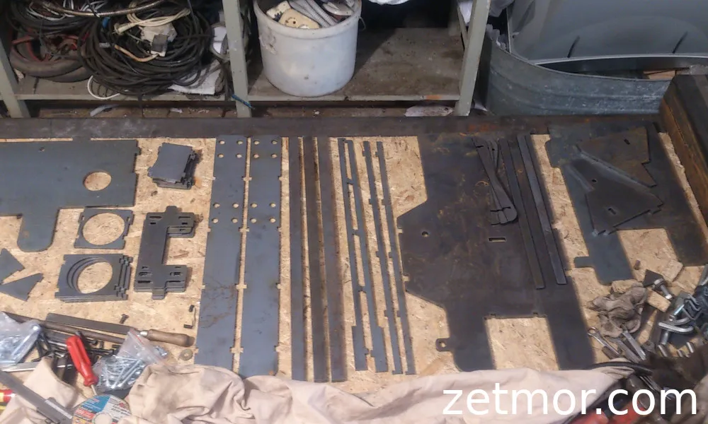
parts will be cut with a laser, then undergo milling for the mounting locations for rail guides.
Anything related to rotation — let’s do it on lathe machines.
(Of course, as usual, ideas and reality don’t always align — but more on that later).
Like many enthusiasts, the dream was simple and bold — to create a universal machine capable of doing everything.
And here’s what I planned to implement:
- Two independent spindles — one for roughing and the second for finishing. Or even working in tandem to reduce cutting time!
(I discarded the automatic tool changer option — too expensive). - Processing tall workpieces — because limiting oneself in size is just boring.
- Lathe processing as a fourth axis: two setup options —
one for “short” pieces with a diameter up to 200 mm and length up to 1 meter,
and another for larger parts — columns, carved balusters, and other large forms. - Modular welded frame — so that if needed, you could disassemble the machine and transport it in a car.
Of course, this solution adds quite a bit of work… but it’s precisely these challenges that make the project truly exciting!
Linear Movements
The market today offers a huge variety of solutions for linear movements, but after long comparisons and studying reviews, I settled on profiled rails from HIWIN — a manufacturer trusted by engineers worldwide and time-tested.
HIWIN linear guides are the foundation for the linear movements of many modern machines and mechanisms. They ensure smoothness, accuracy, and reliability of movement for the components that directly affect the quality of machining. The company offers a full range of series: HG, RG, EG, MG, WE, and their modifications — each designed for specific tasks and loads.
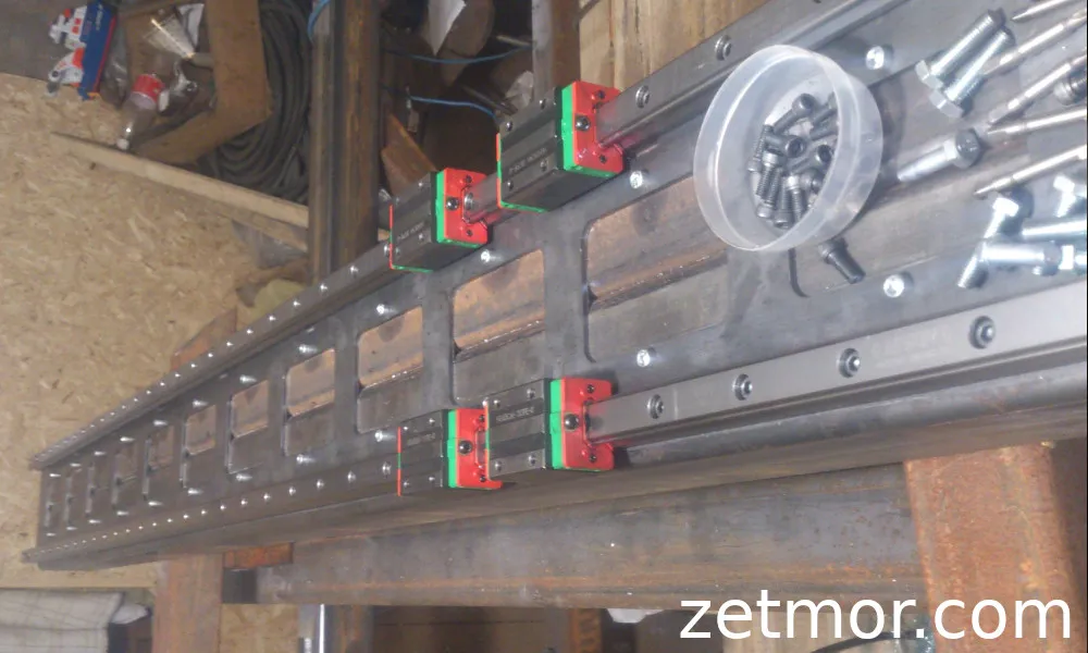
I chose the HIWIN HG series rail guides — a universal, high-load capacity solution perfect for projects where stability and smooth motion are critical.
This series features a special semi-circular profile and a 45° ball contact angle, which compensates for small installation errors, even on imperfect surfaces.
Four rows of balls ensure rigidity and even load distribution in all directions, and the four-point contact between the carriage and the rail makes the system highly stable.
Key Features of the HG Series:
- Self-Alignment
- Interchangeability
- High Structural Rigidity
Marking and Interchangeability
The HG series is divided into interchangeable and non-interchangeable models. The sizes are the same, with the only difference being that in interchangeable models, the rails and carriages can be swapped freely — their accuracy is limited by the P-class, but this is more than enough for most projects.
Accuracy Classes
HIWIN offers several accuracy levels for the HG series rails: C (normal), H (high), P (precision), SP (super precision), and UP (ultra precision). The choice depends on the specific equipment requirements: the higher the class, the more precise but also more expensive.
Preload and Pre-tensioning
For each rail, preload can be set by using slightly oversized balls. This creates a negative clearance, which improves the rigidity and accuracy of the system. However, excessive preload can lead to wear, especially on rails smaller than the 20-series, so it’s essential to maintain balance.
HIWIN distinguishes three standard preload classes:
- Z0 (light preload) — for transport systems, packaging machines, X–Y axes of light industrial devices.
- ZA (medium preload) — optimal for CNC machines, Z axes, milling centers, and measuring systems.
- ZB (heavy preload) — used in heavy machines where maximum rigidity is required.
My Choice
After thorough analysis, I decided on sizes 20 and 25 — with interchangeable carriages and rails.
- For the X and Y axes, I will install HIWIN HG25 rails — ensuring reliable performance with heavy loads.
- For the Z axis, I will use HG20 rails to maintain lightness and smooth vertical motion.
This combination will provide the perfect balance between rigidity, accuracy, and versatility — exactly what my project needs!
Gear Drives
When it came to selecting gear drives, I immersed myself in a world of gears, racks, and screws — with all their characteristics, features, and quirks. After all, how rotation is transformed into linear motion directly affects the smoothness, accuracy, and reliability of the entire machine.
Gear Drives
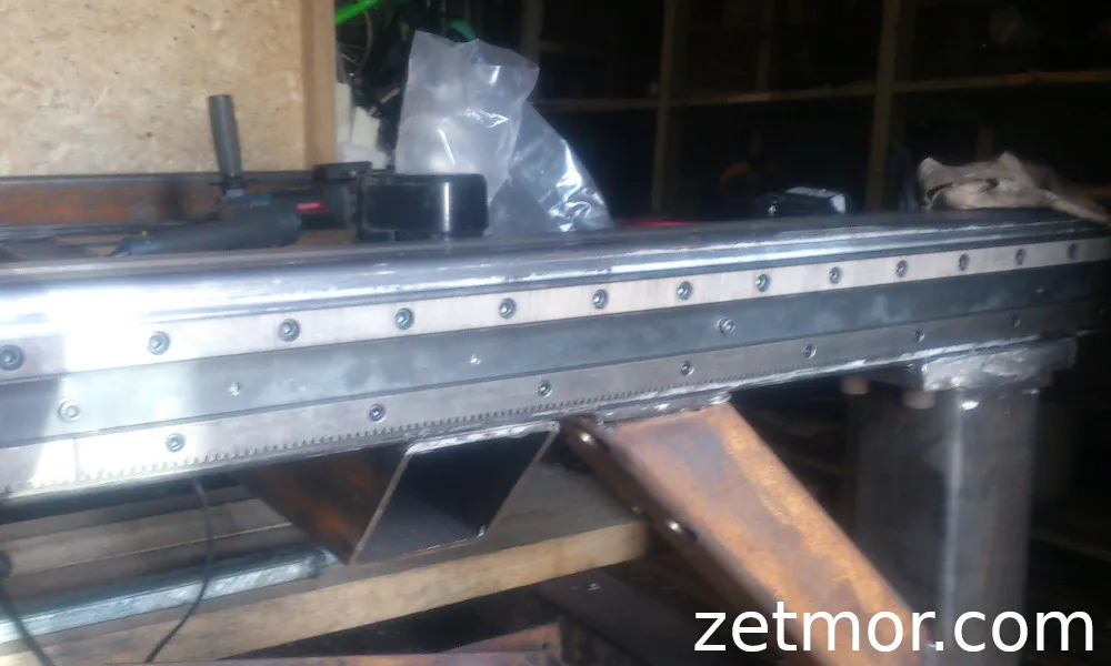
Rack and pinion drive is a classic in mechanical engineering, tested over decades. It converts rotary motion into smooth, controlled linear motion.
There are several types of gear drives: straight-cut, helical, chevron, and rarer Novikov-type (with circular tooth profiles). Each type has its own characteristics. For example, helical gears can transmit greater torque and withstand high loads, but they come with a trade-off — they generate axial forces on the shafts, which requires the installation of thrust bearings to compensate.
In my machine, I decided to use two types of drives — gear and screw. Straight-cut gears are the ideal option for medium speeds and high tooth hardness, where there is no room for dynamic impacts and backlash. On the other hand, helical gears are suitable for more demanding and high-speed components, but require perfect cleanliness and precision during assembly — any speck of dust can ruin the contact and accelerate wear.
Module — the Heart of Gear Transmission
One of the key parameters is the module — a universal value that connects pitch, tooth height, number of teeth, and the diameter of the pitch circle. In simple terms, the module is the part of the diameter “belonging” to each tooth. Without it, it is impossible to calculate any gear drive system.
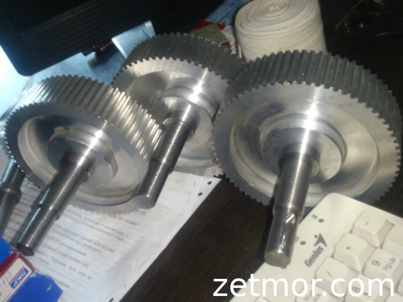
After analysis, I settled on a straight-cut gear with a module of 1.5 — the golden mean between accuracy, strength, and ease of manufacturing.
The Search for Perfection
At first, I was eyeing Gudel racks and gears — precise Swiss-made, simply a dream! But dreams, as we know, come with a price, and in this case — the price of a Boeing wing. Additionally, to install such racks requires an ideal milling base, and in my garage project conditions, that seemed like a utopia.
So, I ended up with Chinese analogs — affordable yet quite decent when installed properly.
For those who decide to go for an ultra-precise project, I would mention world-class manufacturers: KUGEL, GUDEL, GAMBINI, HERION, and others. Each of them produces racks with different accuracy classes and configurations, suited for different operating conditions.
Key Parameters for Calculating Gear Racks:
- Load on the tooth
- Transmitted torque
- Accumulated positioning error per step
- Total positioning error over a 1000 mm length
To evaluate the accumulating error, the following formula is used: nR — number of meshing racks, Gtf — step error, nJ — number of joints, FJ — error of the mounting rail.
Final Decision:
- For long axes X and Y — gear racks.
- For the Z axis — Ball Screw for high precision and rigidity.
Ball Screw — The Ball-and-Screw Drive
A Ball Screw is essentially a magical pair of “screw–nut”, which turns the rotation of a motor into perfectly smooth linear motion. Inside the nut, there are rows of tiny balls that roll between the tracks, minimizing friction.
Ball screws have many parameters: precision, installation scheme, dynamic and static load capacity, acceptable rotational speed, and even preload, which affects the rigidity of the screw-nut pair. The higher the preload — the more stable the system, but assembly precision requirements increase as well.
For all axes, I will install NEMA 34 stepper motors with GeckoDrive G213V drivers, and power will be provided by transformer blocks at the maximum allowed voltage for the drivers. To protect the system during braking, I will add dampers that absorb back EMF.
Gearbox — A Balance of Speed and Force
There are various types of gearboxes: belt, planetary, and gear — each with its own characteristics. Engineers’ opinions differ: some say that a belt gearbox is better for stepper motors, and a planetary gearbox is better for servos.
Servos are indeed cool, but their price can quickly ground dreams. For a DIY machine being built in a garage and out of pure enthusiasm, I chose a belt gearbox.
It will be single-stage, with the maximum possible gear ratio, so the motors will operate in an optimal range, providing high torque at high speeds and low vibrations at low speeds. In simple terms, the gearbox will help achieve steady and precise feed, even with delicate material processing.
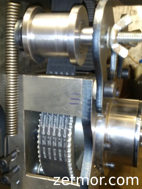
The base will consist of HTD-M5 profile pulleys, a 20 mm belt, tensioners, and a metal housing, custom-machined for the project.
Frame
The frame — that’s classic. A welded structure made from profile tubing, strong, reliable, and modular — so that the machine can be disassembled and transported in parts if needed.
Ideally, I’d love to have milled mounting surfaces for the rails and racks… but for now, that’s a dream.
Designing the frame took me about a year. During this time, the design changed dozens of times, it was refined, adapted, until it finally became the version I decided to bring to life in metal.
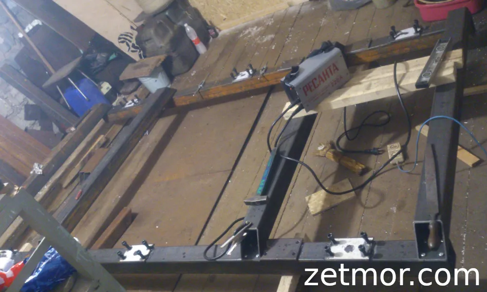
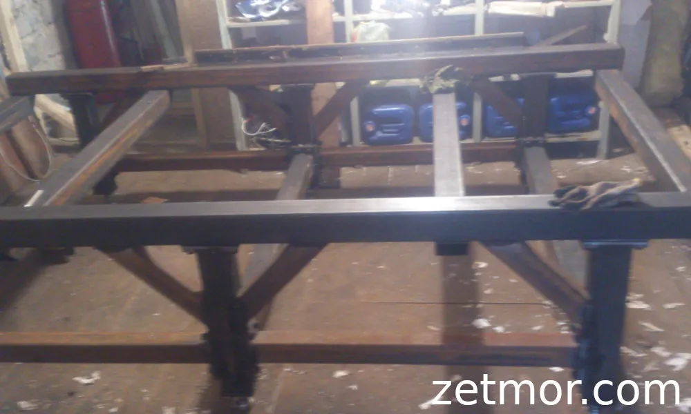
I started the design from the very base — its frame. As I mentioned earlier, the main material I chose was profile tubing, and it’s where the story of my second CNC began.
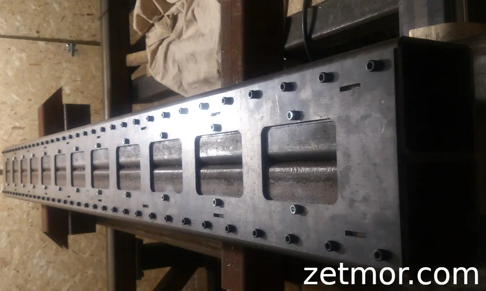
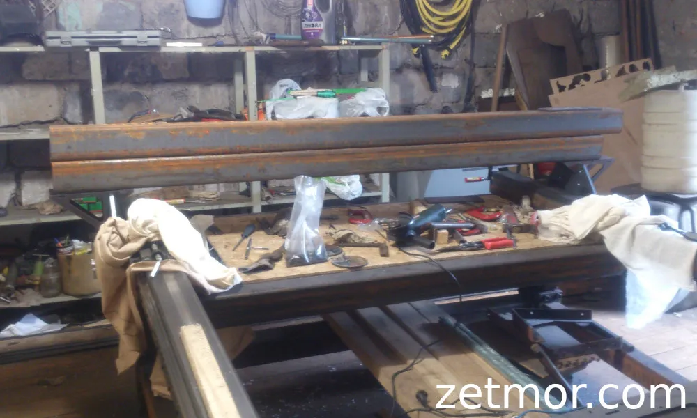
For the HIWIN rails, I used a 100×100 mm tube with a wall thickness of 5 mm, made from structural steel St3. Initially, I wanted to find something thicker — so that I could secure M6 bolts with standard pitch and have enough thread depth. I also planned to mill the surfaces for perfect alignment, which would further consume the metal thickness.
But, as often happens, reality stepped in — suppliers just shrugged and assured me that “only 5 mm is available.” So I decided not to waste time and went with it. All the load-bearing elements of the frame will be made from 100×100×5 mm tubing, and the braces will be made from 80×80×4 mm.
Proportions and Geometry
Since my CNC was initially conceived for advertising production — cutting plastic, plywood, aluminum composite — I based the design on standard sheet sizes: 1525×1525 mm and 1220×2440 mm. These dimensions became the starting point for the frame design, while simultaneously planning for lathe processing capability and enough space for the portal beam.
Equally important was thinking about ergonomics — after all, I’ll be working at this machine. After several mock-ups and calculations, I determined the optimal table height — 600 mm. This height allows for comfortable material loading and doesn’t tire me out during long work sessions. Of course, under the table, I will install adjustable supports — and, as usual, I’ll make them myself.
DIY Constructor
Another idea that seemed great at the start was the modular design. I wanted the machine to be easily disassembled, transported in parts, and reassembled. In practice, this turned into a massive complication — dozens of additional plates and connections appeared, along with the need to select high-strength bolts class 12.9. (If you’re going to do it, do it right, as they say, “just to be sure”).
Now, with the benefit of hindsight, I realize that modularity in real life is almost unnecessary. After assembly, the machine still needs to be realigned, which is a lengthy and painstaking process. But back then, I moved forward with enthusiasm, step by step, turning the idea into metal.
Key Frame Parameters
- Machine working area size — 1700×2800 mm
- Table height from the floor — 600 mm (can be reduced if necessary)
- Plate thickness for supports — 10 mm (about 15 mm for threading)
- Plate thickness for braces — 4 mm
Shape and Solution Search
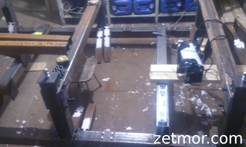
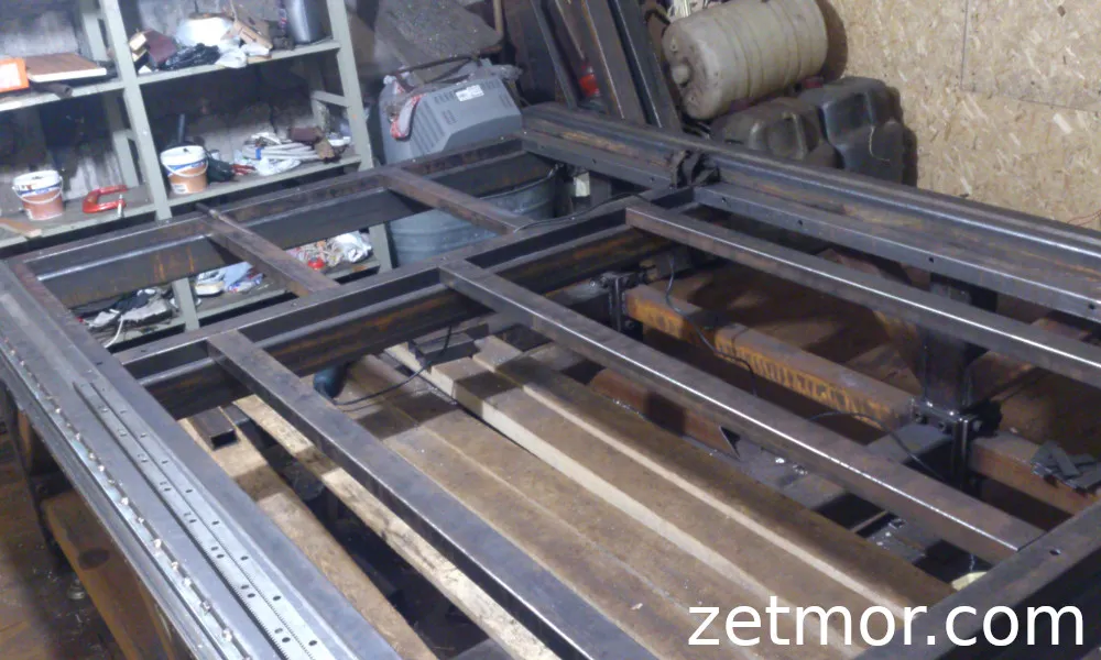
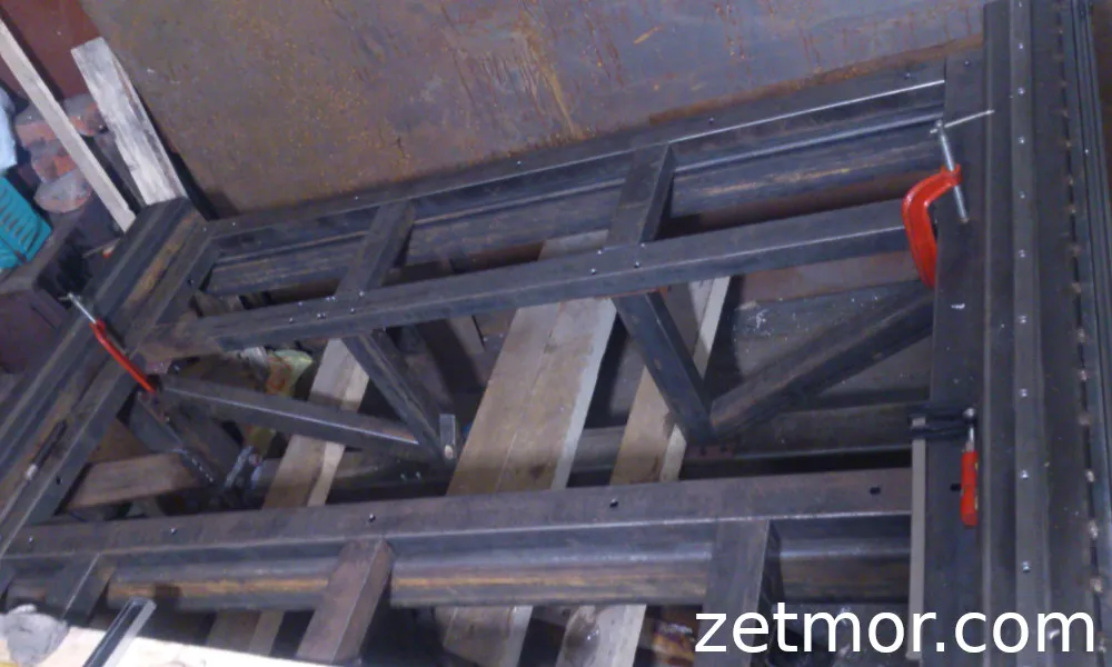
Then came the most interesting phase — searching for the perfect design. Hours of forum browsing, dozens of drawings, photos, solutions from hobbyists and industrial professionals. At first, my frame looked like a simple box with crossbars — at that point, everything seemed logical, but it looked, to put it mildly, unconvincing.
It had to be redone. Over and over, I changed the scheme, added supports, repositioned the braces, experimented with tube connections and dimensions, until I finally came up with a stable and simple six-support design. That’s when I looked at the drawing for the first time and thought: “Yes, now this is the foundation of a real machine.”
Next Step — The Gantry
With the frame more or less figured out, I needed to design the gantry beam with the installed Z-axis, spindle, motors, carriages, and guides. Their layout would determine the final dimensions of the entire base.
As for the lathe functions, I considered the possibility of adding extra modules before assembling the main table — so that I could easily expand functionality in the future.
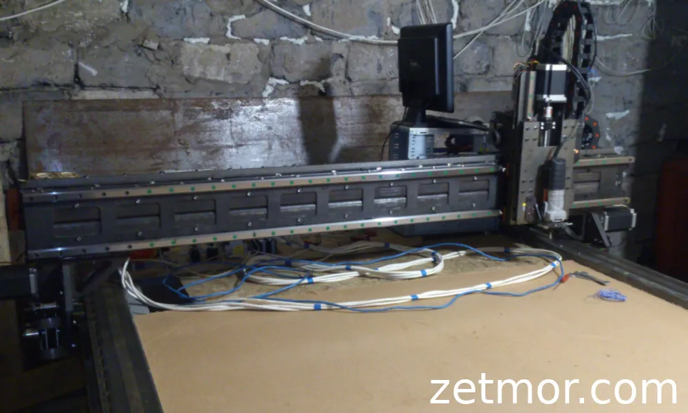
The Gantry
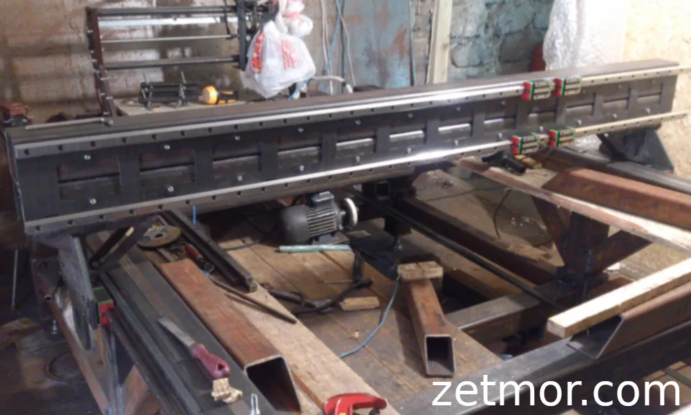
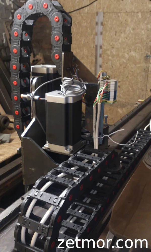
Initially, the gantry was meant to be simple and strict. But, as is often the case in engineering adventures, things got much more interesting along the way! I ended up using 100×100 mm tubes. The top was designed with a neat groove for the flexible cable chain — a small detail, but how satisfying it is when everything is thought through to the last bolt.
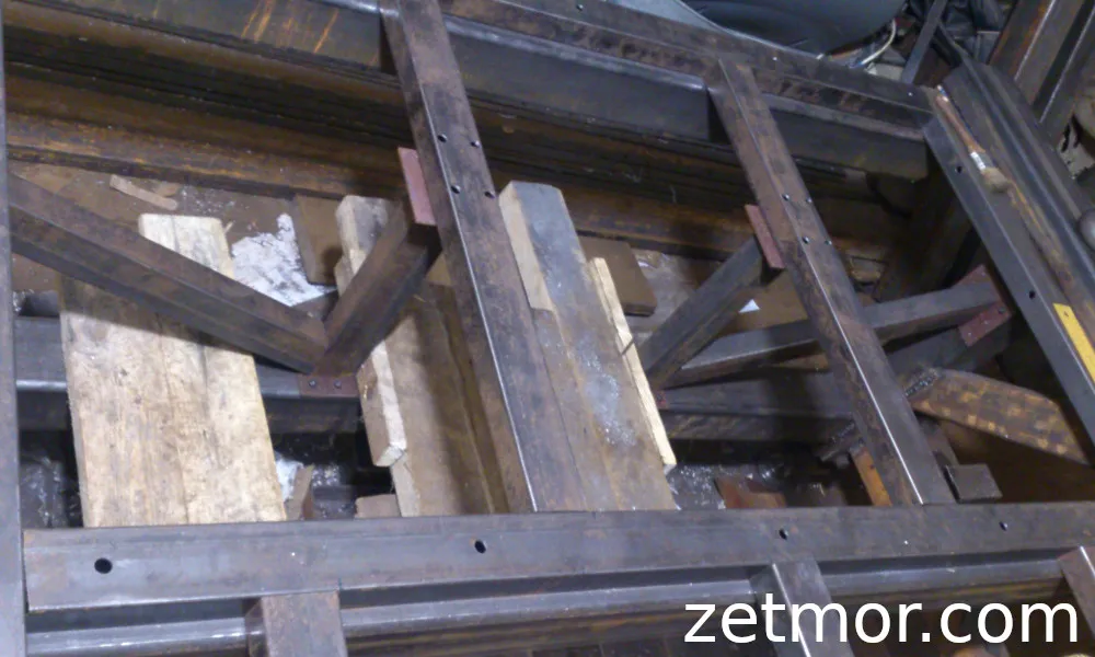
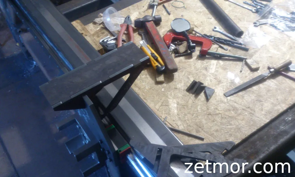
For the Z-axis, I decided to use a sheet of duralumin — an idea I spotted somewhere on the internet, and then I developed my own version. The first sketches of the beam, to be honest, looked a little rough, but they had character! In the early images, you can also spot the previous version of the supports — the traces of that engineering evolution that every project goes through.
I considered lightening the beam by making it out of sheet metal, but I stopped in time — during welding, it would have warped, and that would ruin the precision.
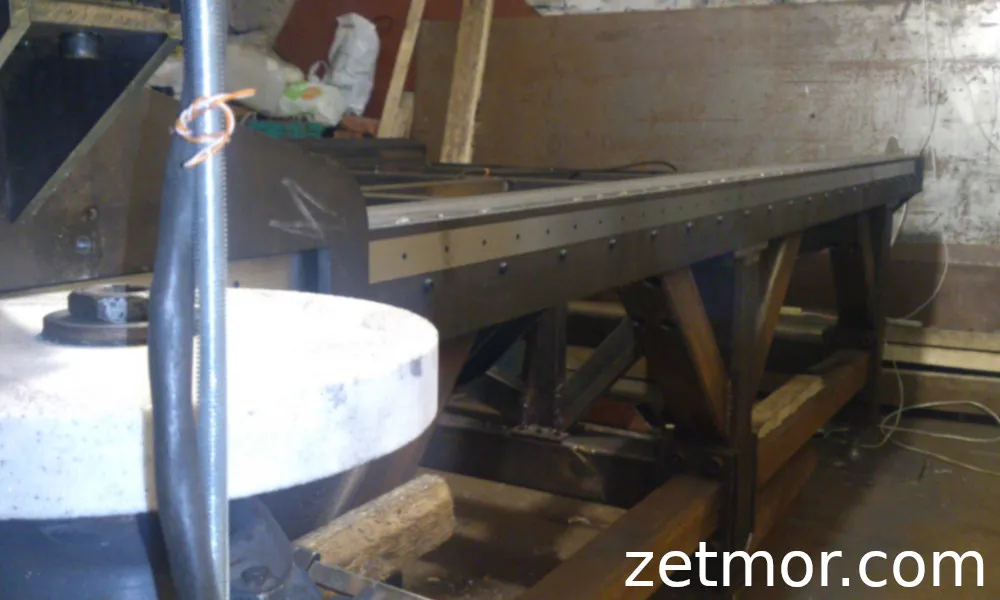
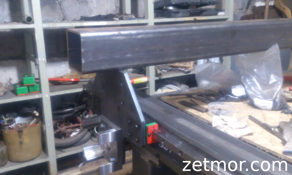
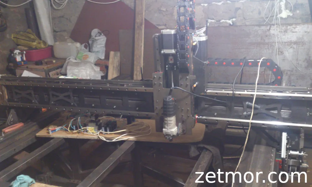
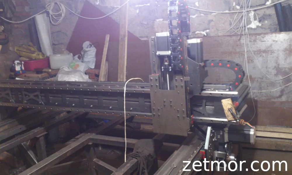
When the beam finally took its place on the machine frame, supported by steel posts, the structure took on new lines.
The gantry ended up wider than the frame itself, and that was no accident. This design allows one Z-axis to park and the other to work on the same piece of material — across the entire working area! In other words, the machine now has the possibility of installing two independent Z-axes, turning it into a truly versatile powerhouse.
Gantry Posts
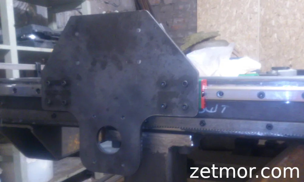
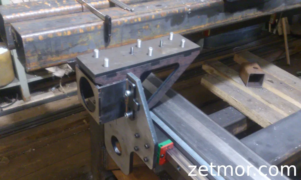
The gantry posts also went through quite an evolution. I had to adapt the design to the capabilities of the available machines, thinking through everything from laser cutting and welding to bolt assembly and milling. At one point, I even considered a mechanical connection between the left and right posts.
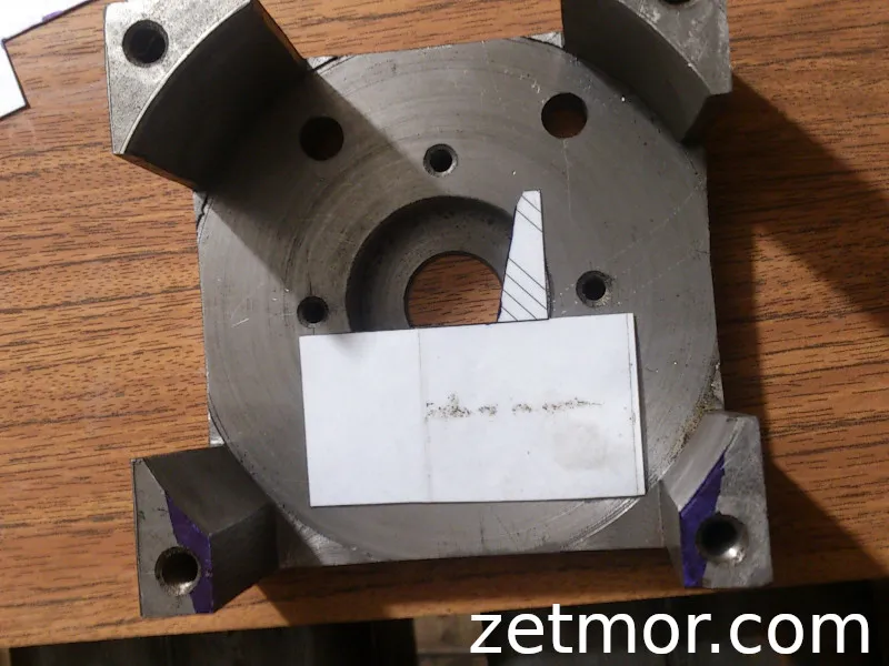
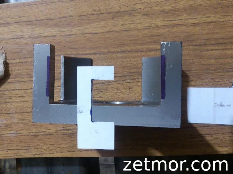
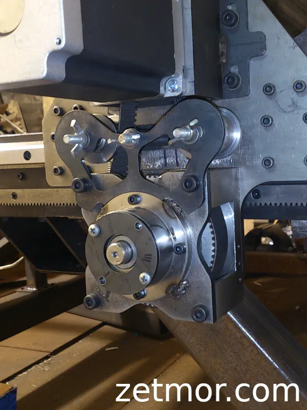
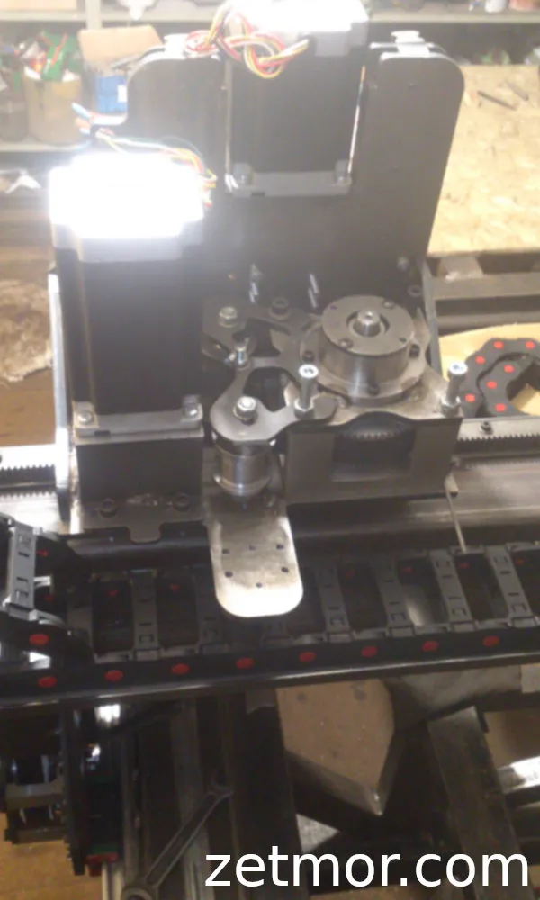
The only part of the old design that survived was the gearbox casing — my “turning square.” Everything else was completely redesigned from scratch.
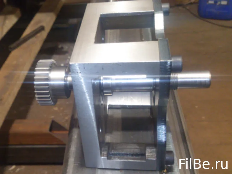
The final posts were made from sheet steel and assembled via welding. The design includes a shaft that connects both posts, and the gearboxes are mounted on HTD-5M-profile pulleys — they can be swapped between the X and Y axes. The mounts for the NEMA 34 motors are standardized and equipped with tensioners for the belts — every detail was thought out for manufacturing in my conditions.
Z-Axis
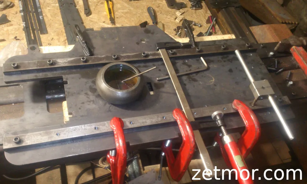
The Z-axis was originally designed to be light but sturdy — I designed it for milling, using D16T duralumin. It was meant to be a classic design, familiar to anyone who’s ever looked at CNC machine drawings. But, as often happens, the final result took a different path.
The final version is completely different. It’s made entirely of sheet steel, with additional mounts for flexible cable chains and terminal blocks on a DIN rail, along with limit switches for safety. The entire structure became more compact without losing rigidity.
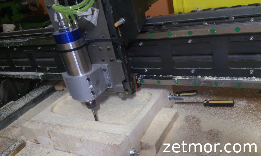
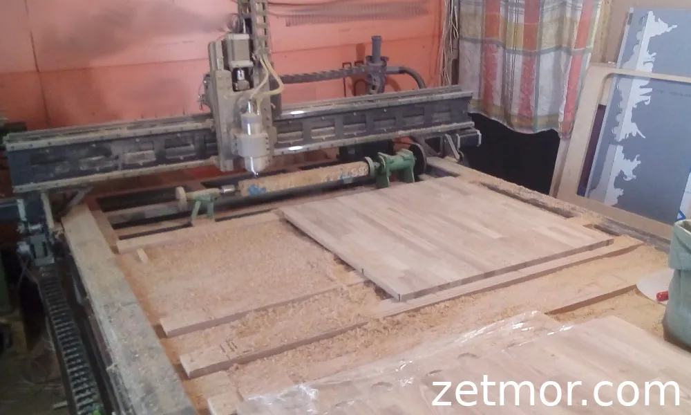
I installed a 2.2 kW water-cooled spindle. Why this one? Simple: quiet operation. After the deafening roar of the manual spindle from “Interskol,” this one is like the rustle of wind compared to a rock concert. It works powerfully, confidently, and at the same time, it doesn’t drive me crazy with noise.
Electronics
The system is built around the reliable Geckodrive G213V drivers, which have been with me since the first machine. Back then, I chose them “with a margin,” anticipating future needs, and it turns out that was a wise decision. These little guys can handle up to 80 volts, and I decided to get the most out of them.
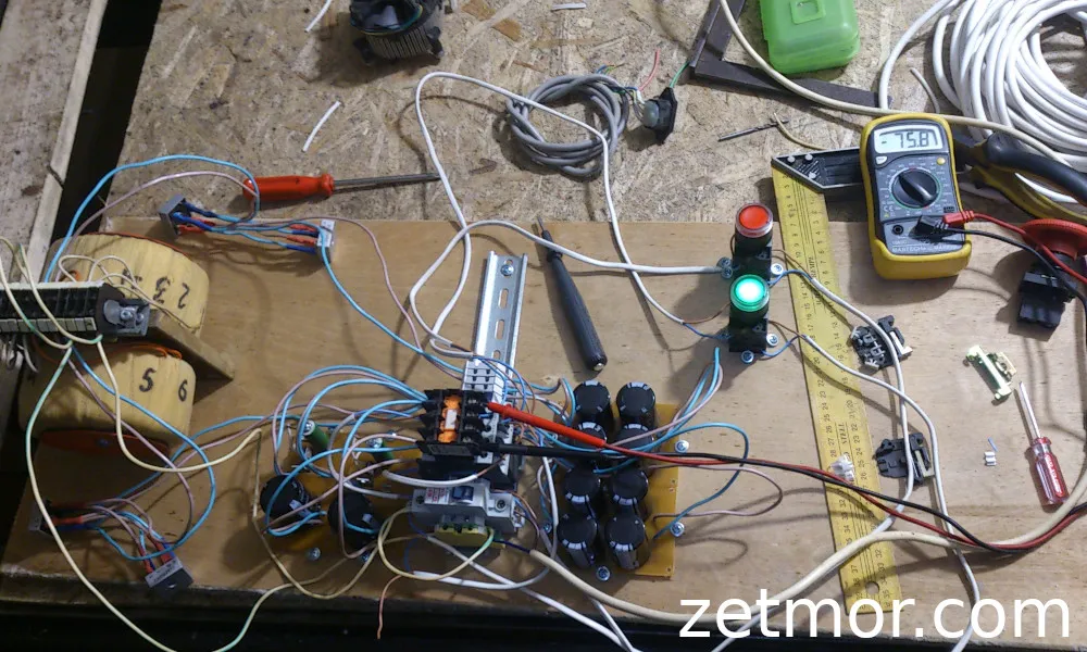
Knowing the maximum voltage, I ordered transformers wound to provide that voltage, so that after rectification and smoothing of the ripple, I would get around 76 volts DC — almost the maximum. Why? It’s simple: the higher the voltage, the faster the current grows in the stepper motor windings, resulting in sharper response and better dynamics.
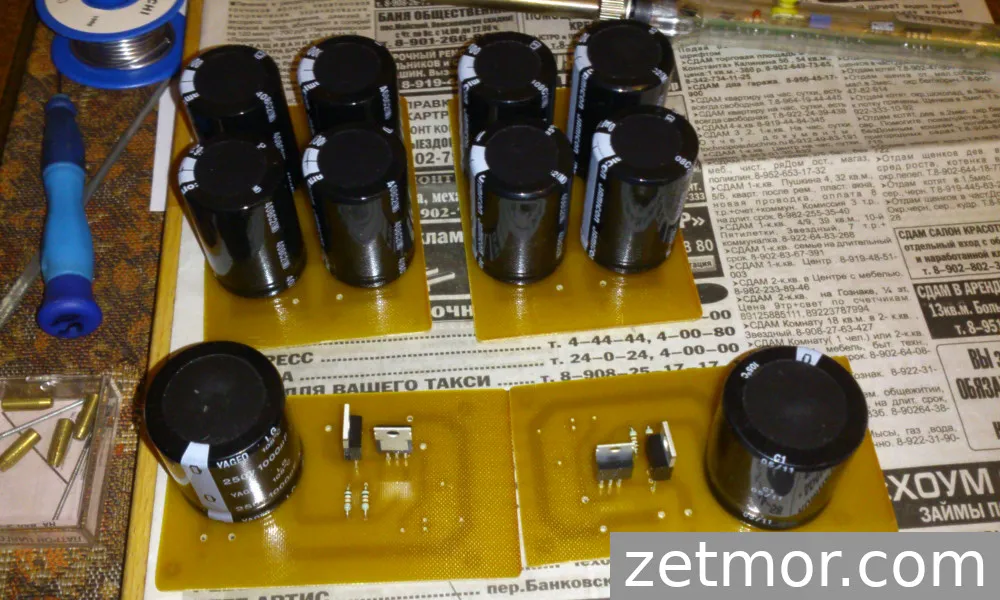
While the winders were working on the transformers, I didn’t just sit around. I assembled damping boards to suppress the spikes generated by the motors when braking. Back EMF can damage the driver, so I redirect it to a powerful resistor, turning electrical surges into harmless heat. Additionally, I included electrolytic filters to keep the power supply clean, free of ripple and noise.
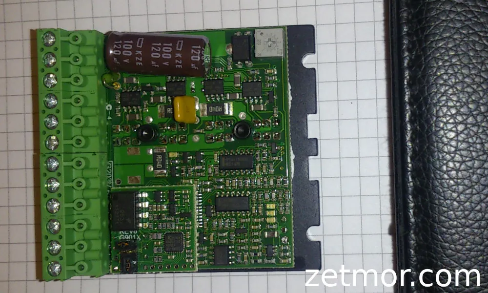
The connection between the computer and the drivers is maintained by an optocoupler board. It worked faithfully for several years until one day it died. By that time, I had already gotten the hang of electronics, so instead of panicking, I grabbed the soldering iron, spent 60 rubles on a new chip, and within an hour, everything was running again.
In moments like these, you really feel it — this is your machine, your system, made not according to someone else’s blueprints, but from your own understanding and experience.
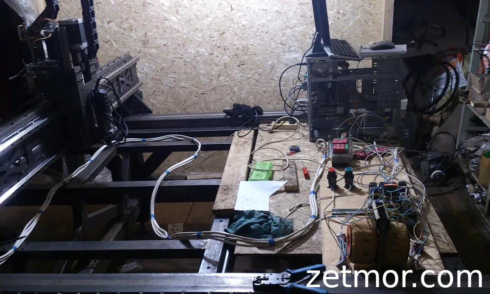
And of course, there was no shortage of countless small details — the ones that turn a simple piece of metal into a true machine:
- Cable tray and channel mounts
- Terminal block holders on a DIN rail
- Pipe caps with emergency stop buttons
- Limit switches preventing accidents
- And dozens of other “small things” without which the machine would just be a pile of metal
Conclusions
In the end, after numerous revisions, mistakes, and nights spent over blueprints, I ended up with a machine that truly works as intended. Every component is the result of personal experience, experimentation, and compromises dictated by real capabilities and available tools.
Yes, it’s not perfect from an industrial production perspective. But for me, what mattered was something else: to build everything myself, adapt the design to the available resources, while maintaining precision and reliability.
This project became not just a machine build, but a real learning process that showed how crucial it is to think constructively, look for solutions, and not be afraid of experiments.
And most importantly, now I know that nothing prevents quality work if approached creatively and patiently — even when the budget is limited and expensive machines are out of reach.
After working on the machine, I wanted something new — I added a lathe axis.