CNC Router from Plywood. A DIY Desktop Gantry Type Machine Project
Part 1
It seems that interest in budget CNC machines is still strong. After browsing the internet, I decided to gather interesting designs of homemade machines and create drawings based on them, including my own modifications or without any. To start, let’s begin with the most budget-friendly option: a plywood CNC machine.
We will design two variants of desktop CNC machines made from plywood for self-assembly. The first will have a movable portal, and the second will have a movable table. In the third part, we will describe the electronics of these machines and their setup for operation with Mach3 control software.
The working area of the homemade CNC machine is 500x400mm, and the Z-axis travel is 50mm.
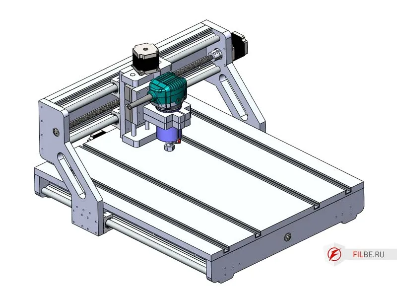
CNC machines with a movable portal make up the vast majority of all CNC routers. Unlike machines with a movable table, in this design, the portal itself moves along the X-axis instead of the table. This configuration removes size limitations. However, it complicates things because it’s often quite difficult to design a portal that, on the one hand, is light enough for movement with the required accelerations, but on the other hand, is rigid enough to avoid flexing under load. Nevertheless, a movable portal is a more flexible and versatile solution.
Key Components of the Machine:
-
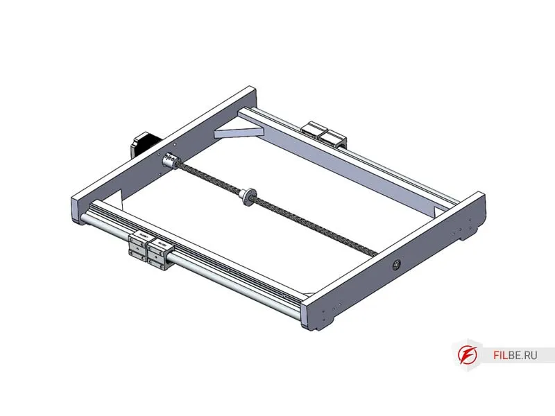
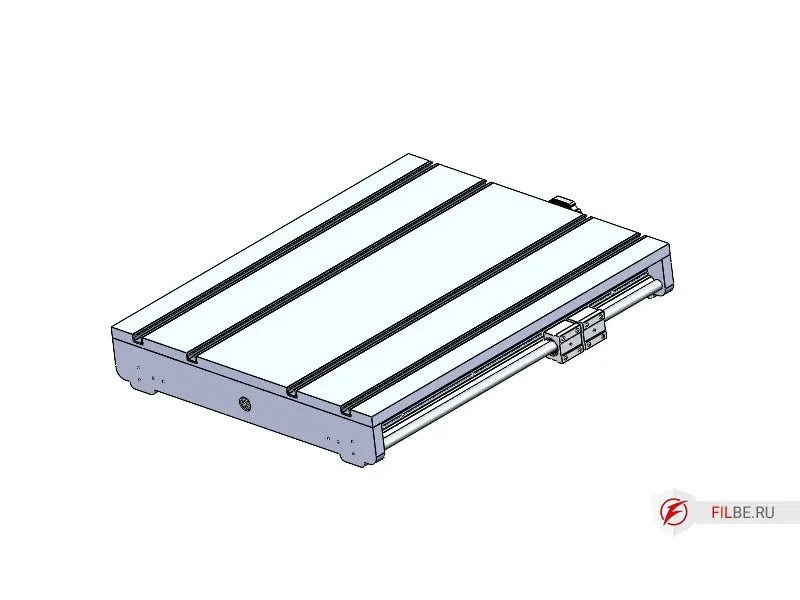
Machine Table (X-axis) – The base to which 16mm cylindrical rails (SBR16) with carriages and SBR16UU roller bearings are attached. The base will be made from 18mm plywood, with grooves in the tabletop for installing aluminum profiles, commonly known as T-tracks, which serve as T-slots for securing workpieces. The supports will have machined recesses to install a 627 bearing and a NEMA 23 motor. The X-axis drive is a 12mm trapezoidal lead screw with a 3mm pitch and a brass nut.
-
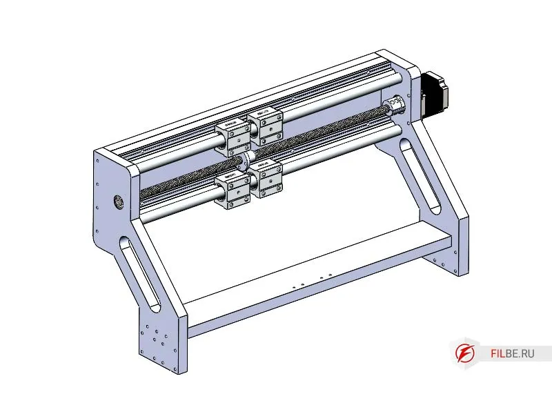
Portal (Y-axis) – Made from 18mm plywood, the rails are the same as those on the X-axis (SBR16), with a 12mm diameter and 3mm pitch trapezoidal lead screw (Tr12x3) and a brass nut.
-
Z-axis – Made from plywood, the rails will be 12mm hardened steel shafts with four SBR12UU carriages to move the platform with the spindle. The mounting is designed for a handheld router such as Makita, Bosch, or similar models. The Z-axis drive is a 10mm trapezoidal lead screw with a 2mm pitch (Tr10x2) and a brass nut.
Materials and Components for the Plywood CNC Machine
-
Trapezoidal Lead Screws
- 12mm diameter, 3mm pitch (X,Y axes) (2 pcs.)
- 10mm diameter, 2mm pitch (Z axis) (1 pc.)
-
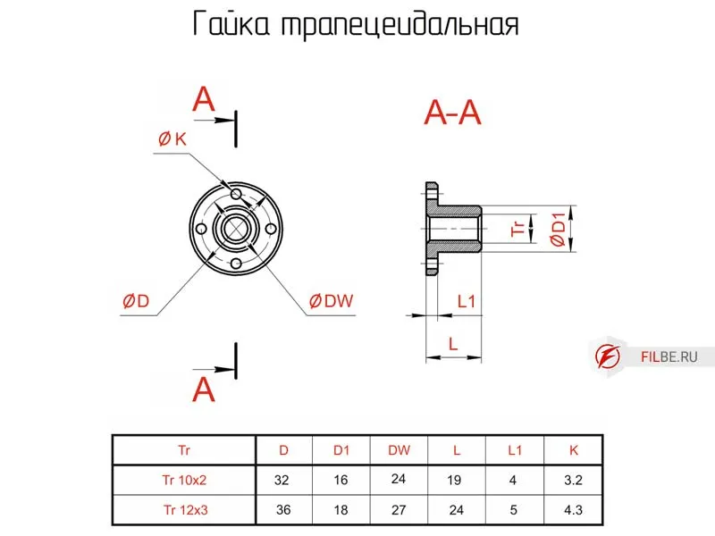
Trapezoidal Nuts
- 12x3 (2 pcs.)
- 10x2 (1 pc.)
-
Two couplings (36mm length, 25mm diameter) with 10x6.35mm diameters
-
One coupling (25mm length, 20mm diameter) with a 6.35x6mm diameter
-
627 bearing (80027) (3 pcs.)
-
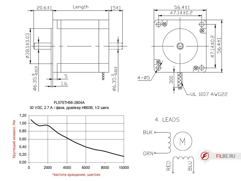
Three NEMA23 stepper motors
-
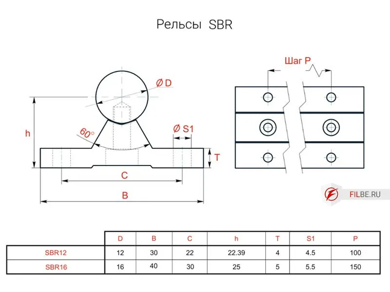
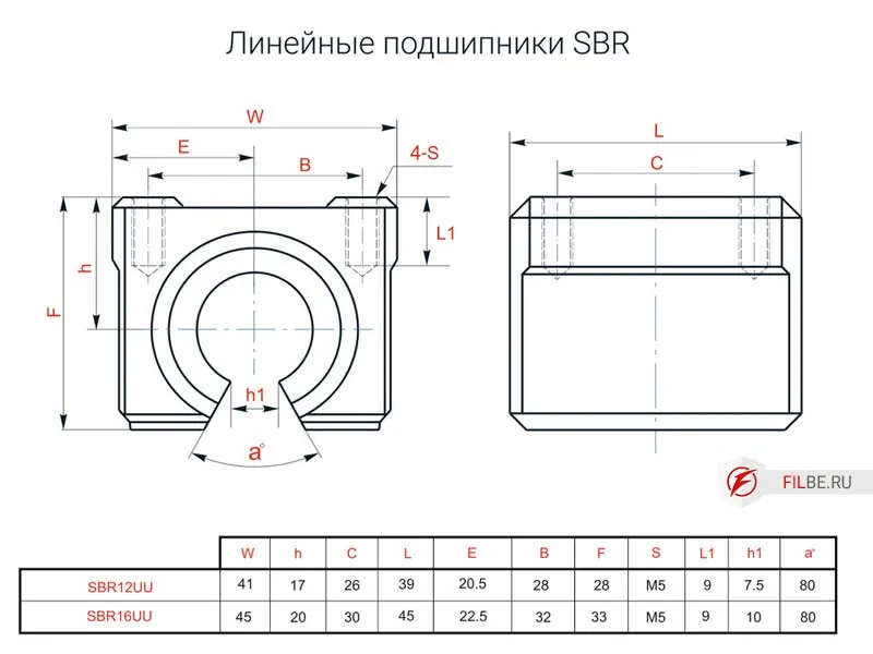
SBR16 cylindrical rails for the X, Y axes
-
Polished 12mm shafts (2 pcs.) for the Z axis
-
SBR16UU carriages for X, Y (8 pcs.) and SBR12UU for Z (2 pcs.)
-
Laminated FSF plywood, 18mm thick
-
Wood screws
-
M5 bolts and nuts
-
Epoxy resin for bonding (optional, adds rigidity)
Component Drawings for this Project
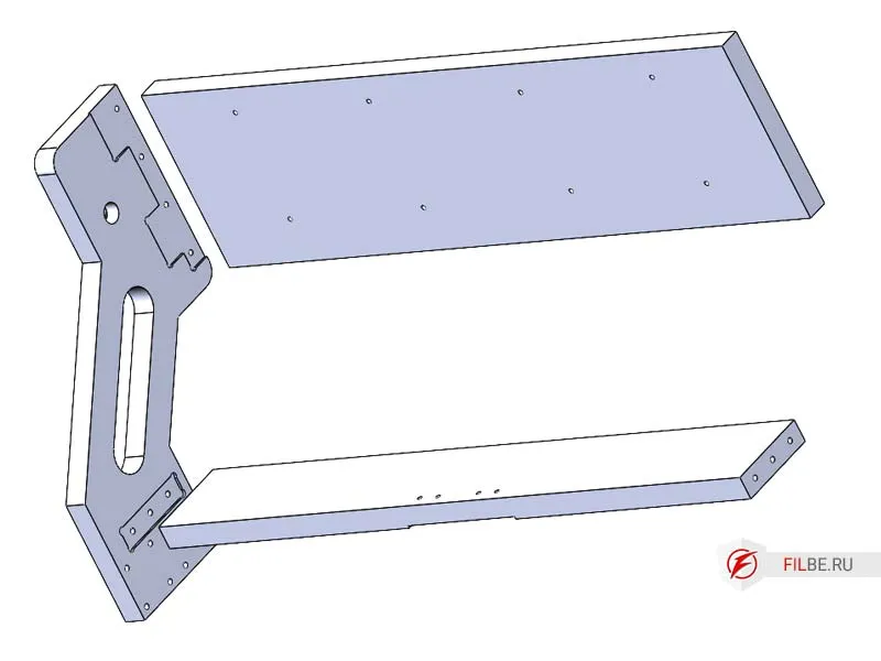
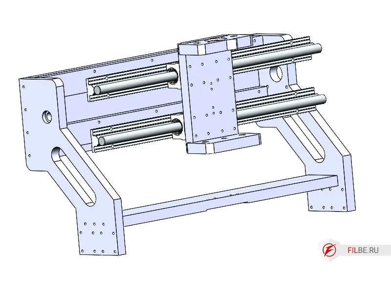
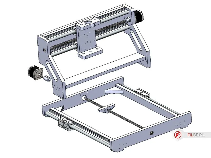
Exploded Diagrams Showing the CNC Machine Parts
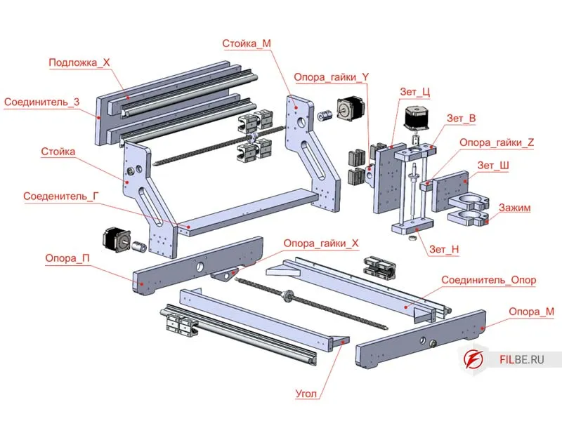
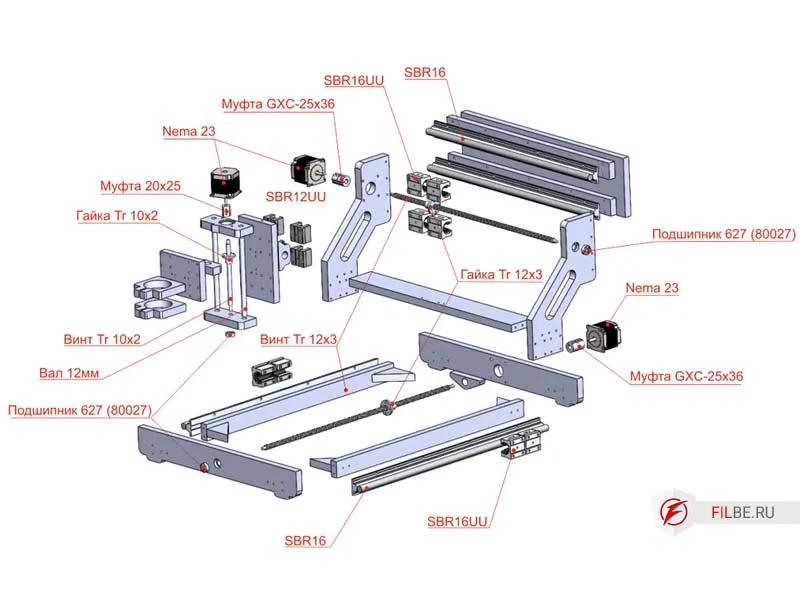
Assembly of the CNC Machine Parts
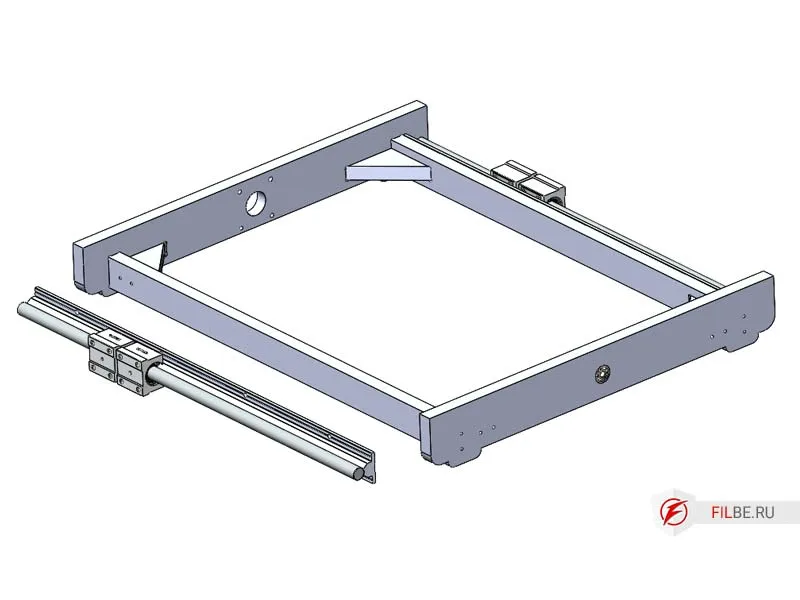
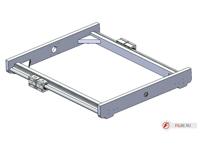
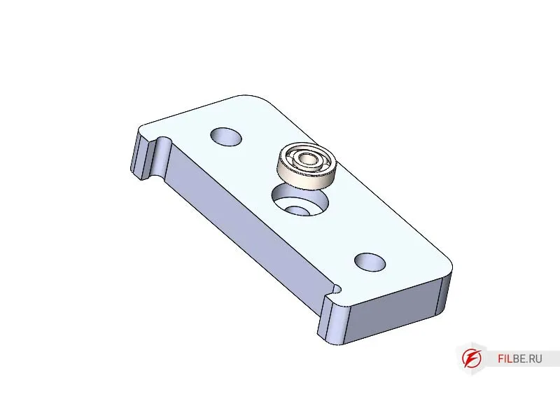
Assembling the Machine Base
-
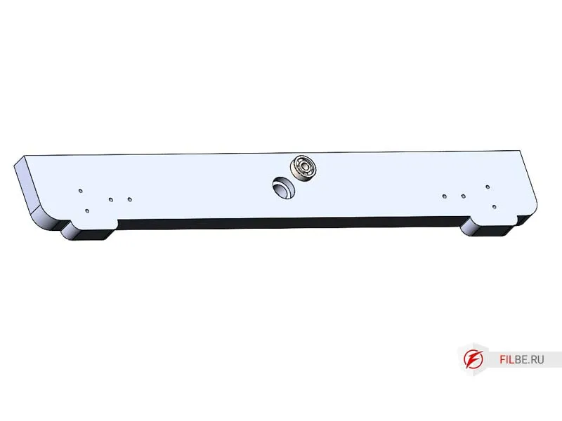
Press the 627 ball bearing into the Base_M part.
-
Take the Base_M, Base_P, Connector_Bases parts, and insert the Connector_Bases into the machined recesses, securing them with screws.
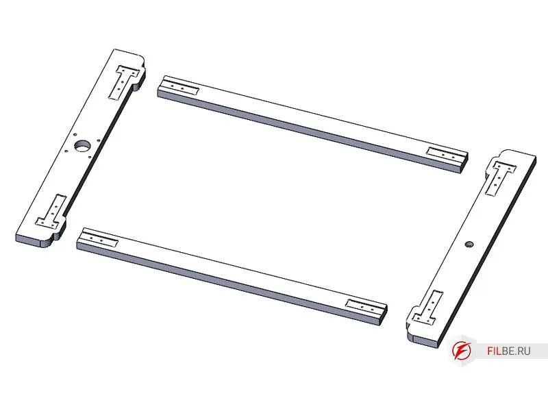
-
Install the corner reinforcement part.
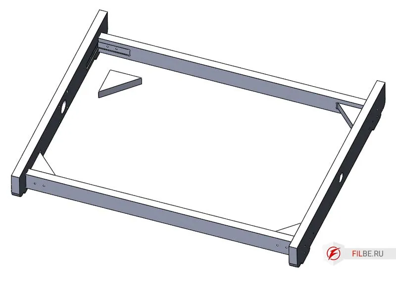
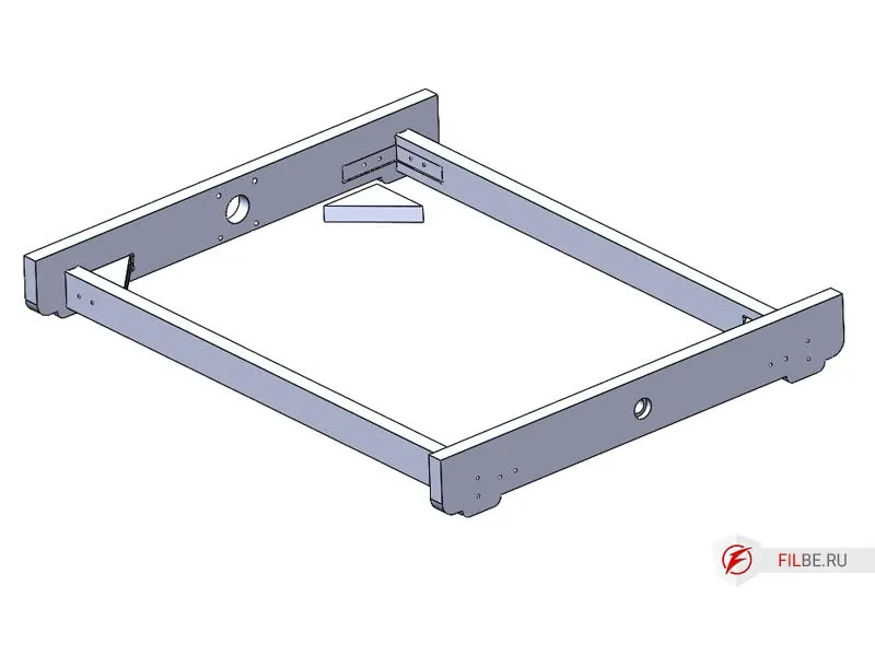
-
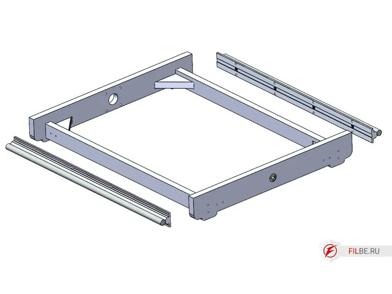
Attach the SBR16UU carriages to the guides.
-
Install the SBR16 cylindrical guides (base supports are aligned with the rail supports, ensuring everything is level). Drilling is done on-site.
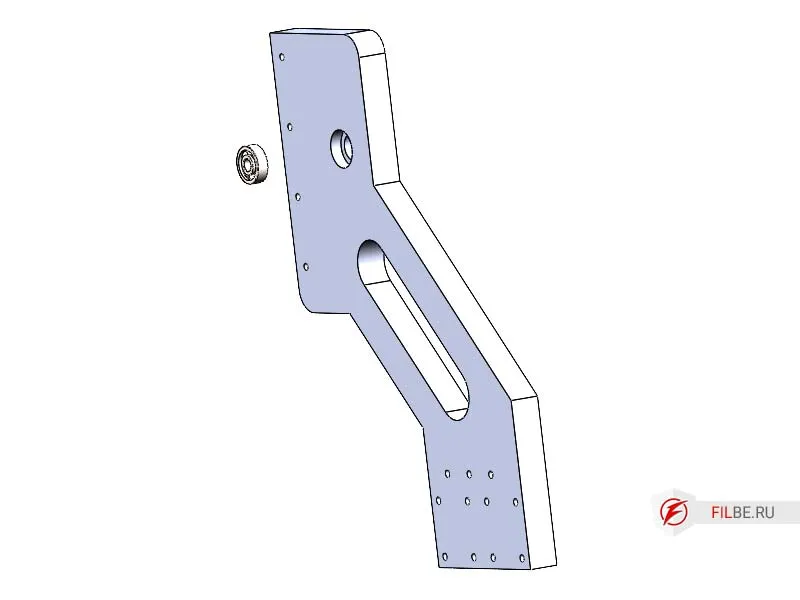
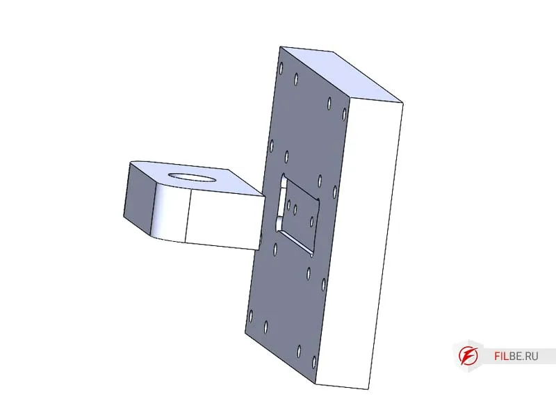
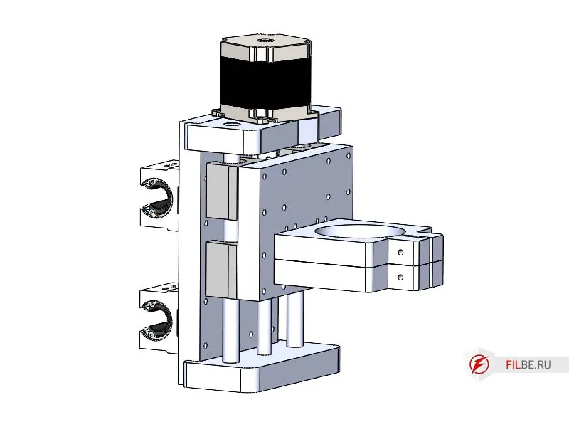
Assembling the Z-Axis of the Machine
-
Install the part Nut_Support_Y into the part Z_C
-
Press the 627 bearing into the part Z_N
-
Install Z_B and Z_N onto Z_C
-
Screw on the carriage guides of the portal
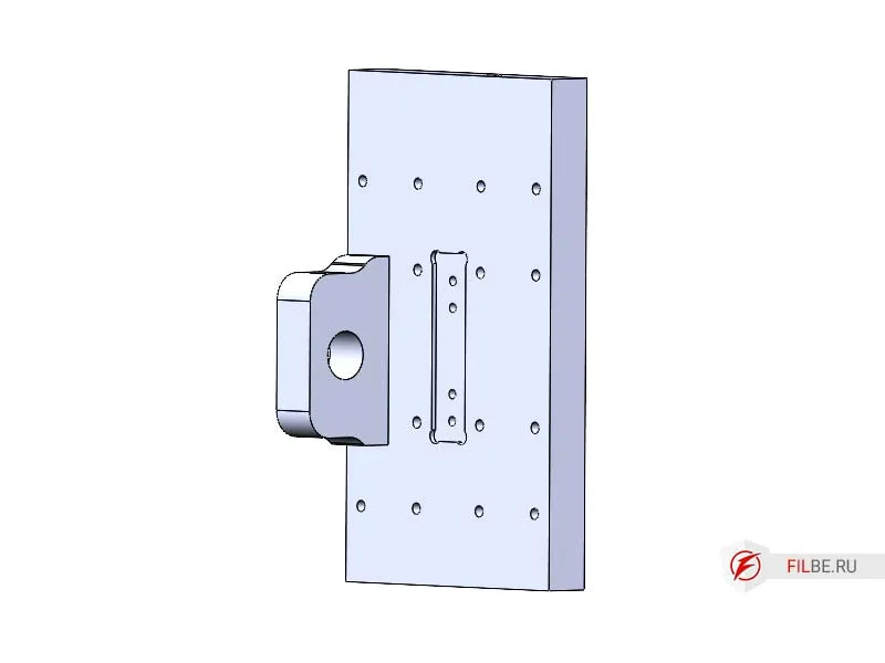
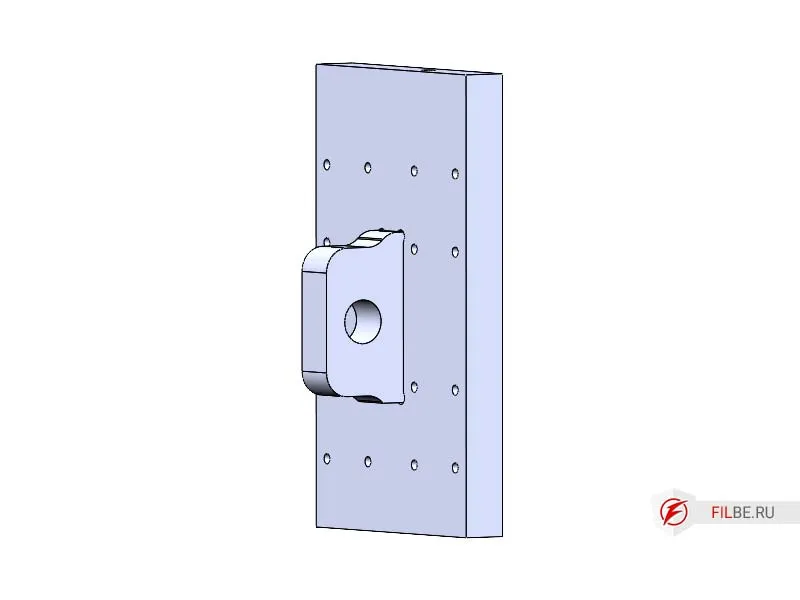
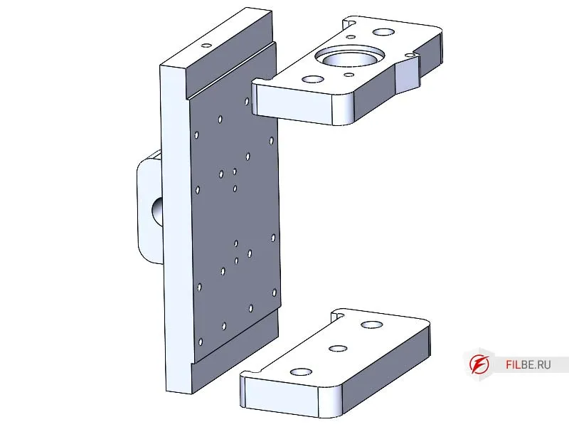
Assembling the Machine’s Portal
-
Press the 627 ball bearing into the Stand part
-
Install Connector_3 and Connector_G into the stand
-
Install the Spacer_X
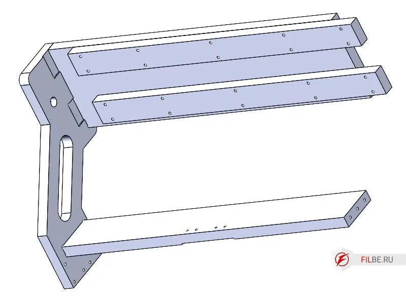
-
Install the Stand_M part
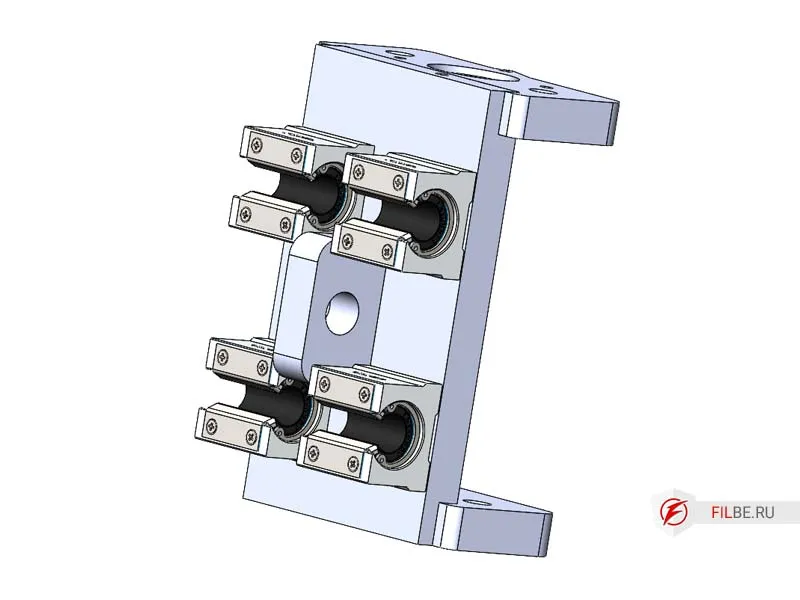
-
Place the Z-Axis on the guides
-
Install the cylindrical SBR16 guides
-
Move the Z-axis towards the motor
-
Install the lead screw and don’t forget to screw on the nut
-
Install the coupling on the Nema 23 motor shaft, connect it to the screw, screw the motor to Stand_M, and secure the coupling.
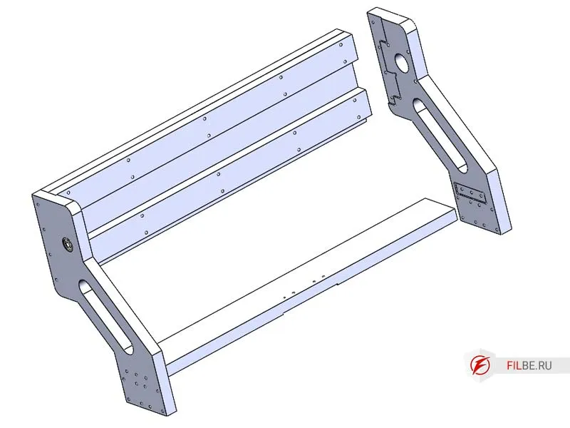
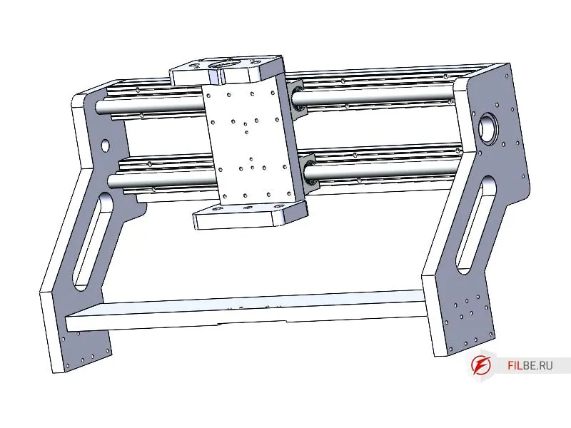
Assembling the CNC Machine from the Prepared Components
-
Install the portal onto the base carriages and screw it down
-
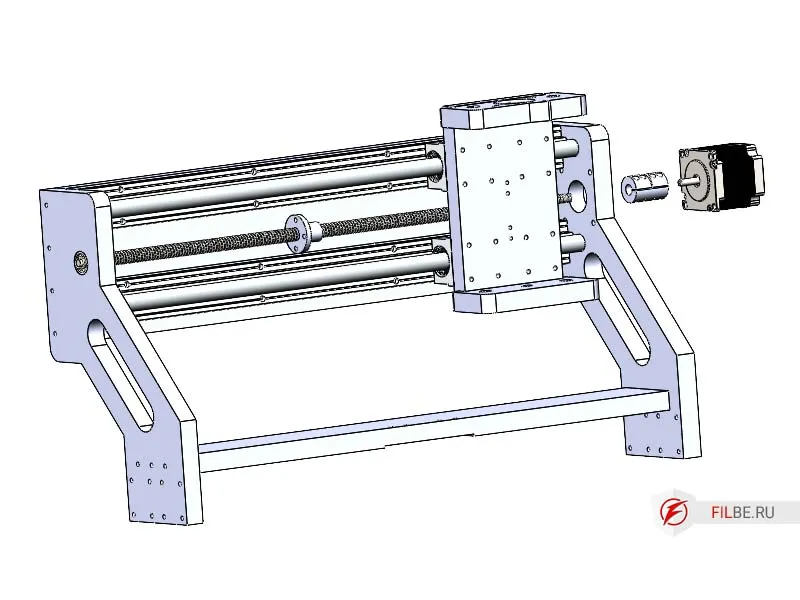
Move the portal towards the motor installation area
-
Install the lead screw
-
Install the coupling on the Nema 23 motor shaft, connect it to the screw, screw the motor to Nut_Support_P, and secure the coupling.
-
Attach the Nut_Support_X to Connector_G
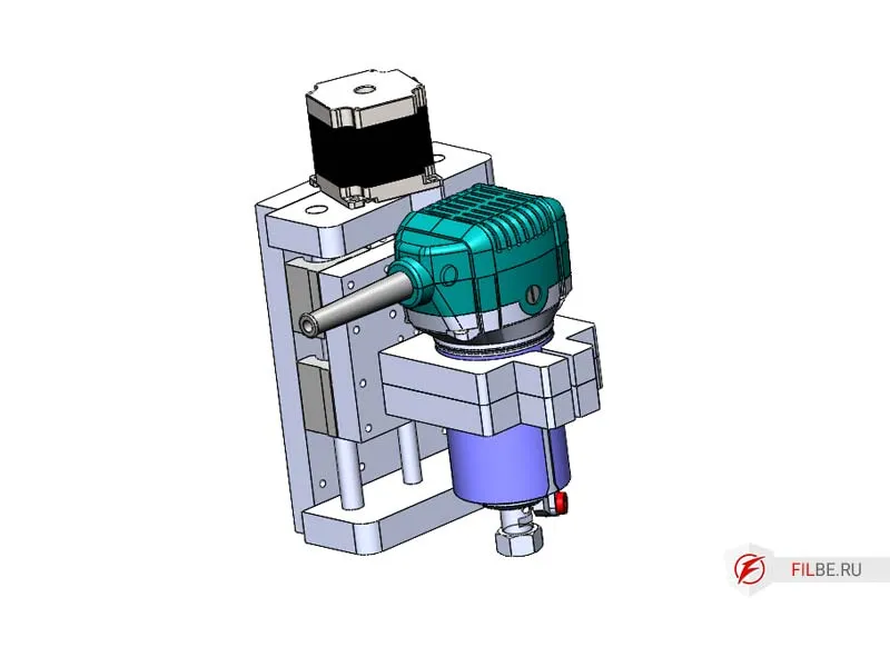
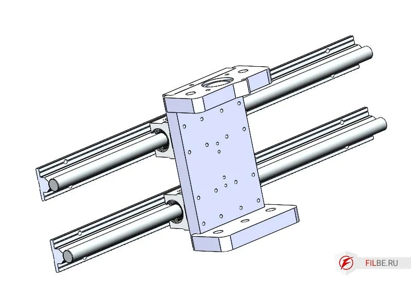
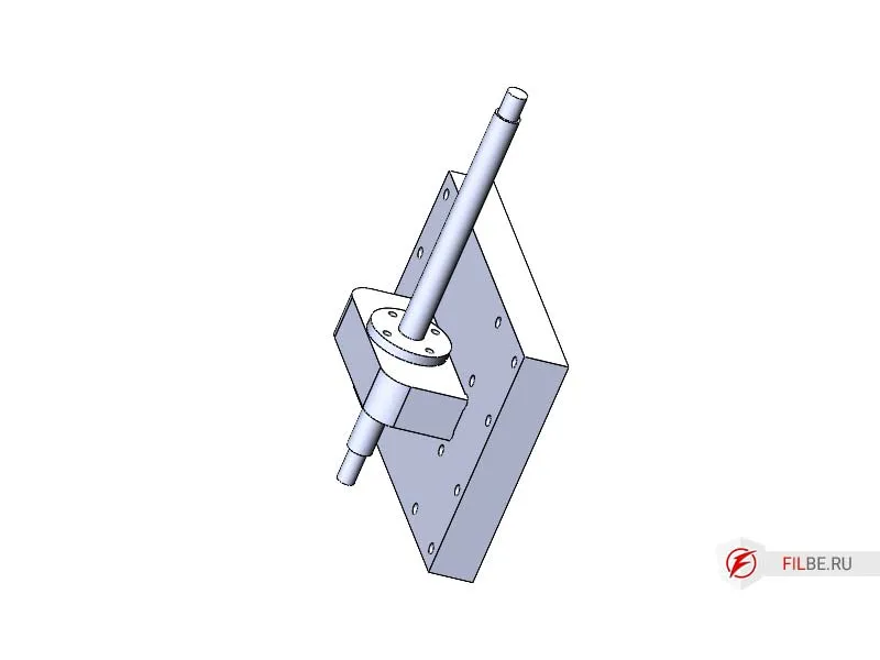
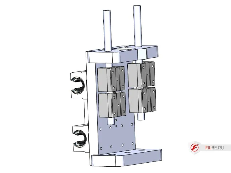
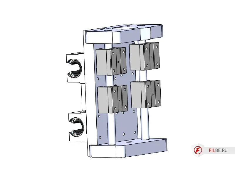
Z-Axis
-
Install the Nut_Support_Z onto the part Z_Sh
-
Screw the Tr10x2 nut onto the lead screw of the Z-axis and install the screw into Nut_Support_Z
-
Press the shafts, install the SBR12UU carriages, and press them all the way
-
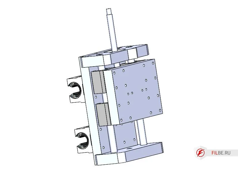
Screw Z_Sh onto the Z-axis carriages
-
Install one end of the lead screw into the bearing, and attach the coupling to the other end
-
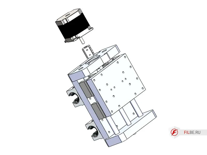
Install the motor, secure the motor, and tighten the coupling
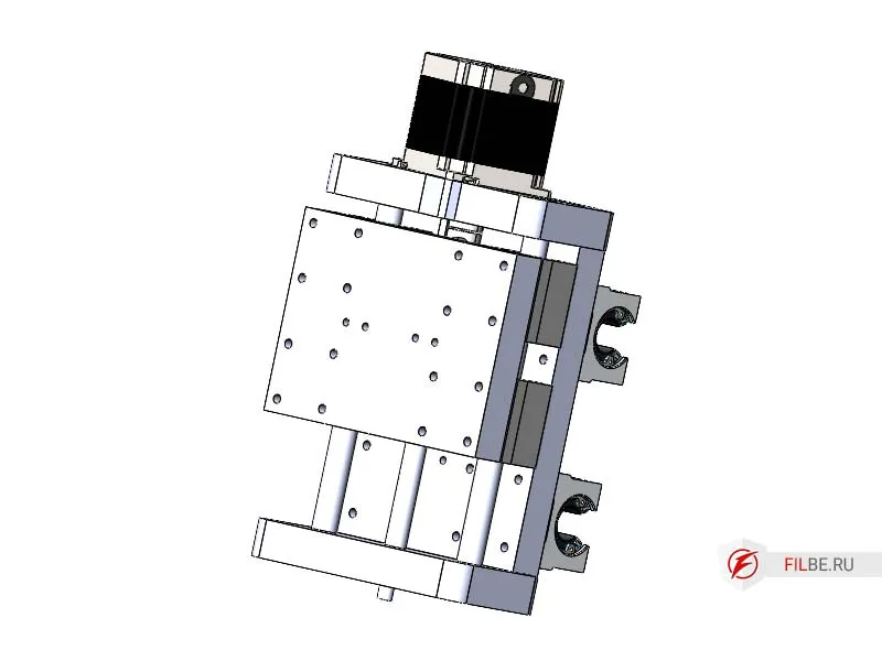
-
Install the spindle clamps on Z_Sh (clamps can be made in various shapes depending on the spindle)
-
Screw the countertop onto the machine, after previously installing the aluminum profile into the milled grooves
-
Install the spindle (mill)
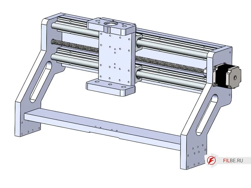
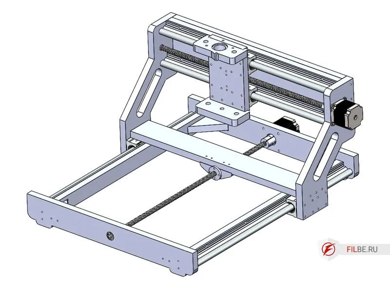
Thus, the assembly of the plywood CNC machine is complete.
Here’s what the machine looks like:
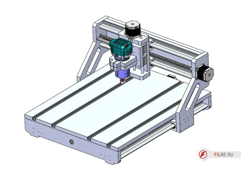
This concludes the first part of the article about desktop CNC machines that can be assembled by hand. I have tried to provide a detailed explanation of all the components of the plywood machine with a movable portal and its step-by-step assembly.
In the next part, we will discuss a machine with a movable table.
Electronics, wiring, and Mach3 setup will be covered in the third part.
You can purchase the blueprints for DIY manufacturing here.