CNC Router from Plywood. A Project for a Desktop Router with a Moving Table
Part 2. The second part of a trilogy on DIY CNC desktop routers made from plywood. A DIY CNC router with a moving table.
This is the second part of a trilogy on desktop CNC routers that you can build yourself.
The first part is hereIn this part, we’ll look at a project with a moving table and go through the details of how to assemble such a machine.
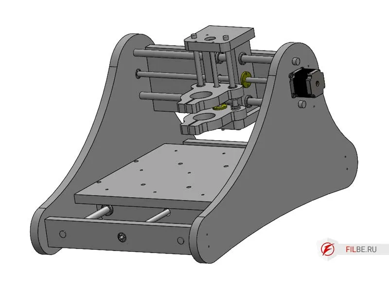
The working area of the DIY CNC router project is 350x270 mm, with a Z-axis travel of 70 mm.
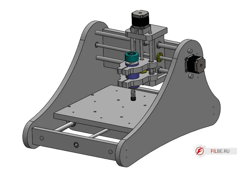
CNC routers with a moving table are a small subset of the entire family of CNC routers. This is because their working area is significantly smaller than that of routers with a moving gantry of the same size. However, they have their advantages. These routers are usually compact and save space. They are suitable for small jobs where high precision and ease of use are important. If you’re reading this, you’ve likely already explored different types of CNC router configurations and know what you need. Let’s get to it.
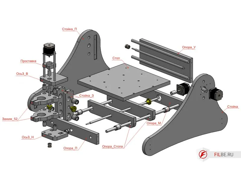
Main Components of the Router
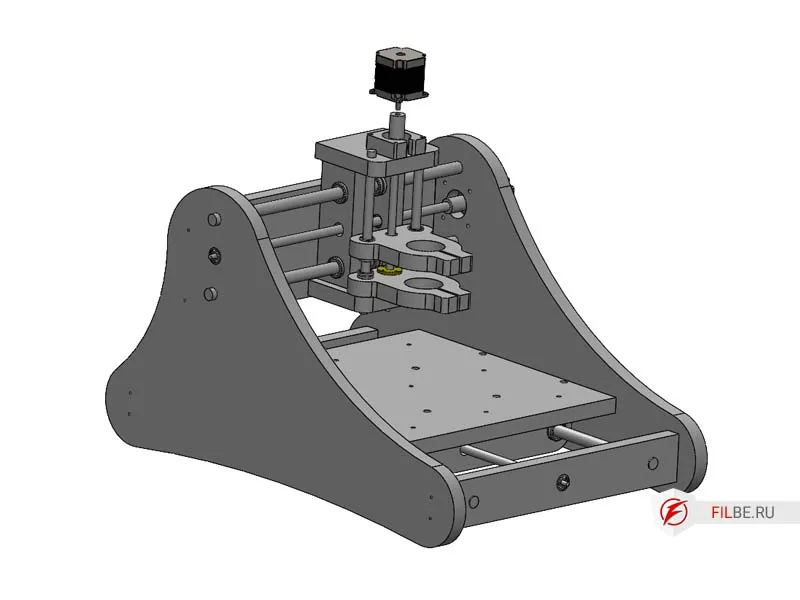
The machine consists of 15 plywood parts, which can be easily cut out by hand. This project does not require specialized tools, and the assembly can be done with basic equipment.
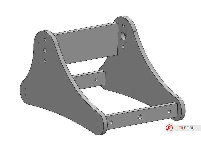
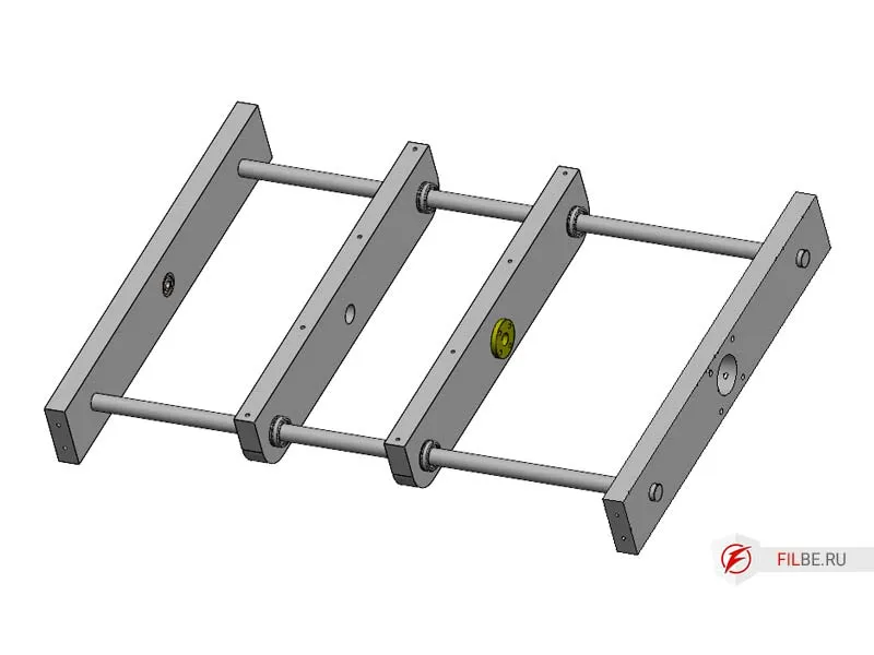
Base of the Router
The frame is the foundation where the cylindrical rails (16 mm diameter) and cylindrical carriages are installed. The X and Y axis rails are pressed into the plywood, and the carriages are also pressed. This helps save on both fasteners and the rails themselves.
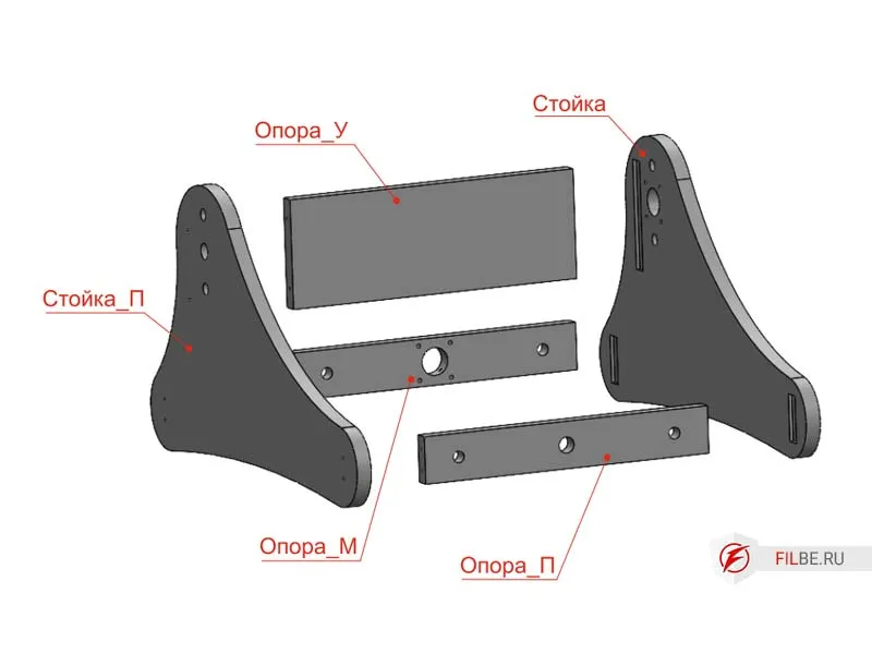
Components of the frame:
- Post
- Post_P
- Support_M
- Support_P
- Support_Y
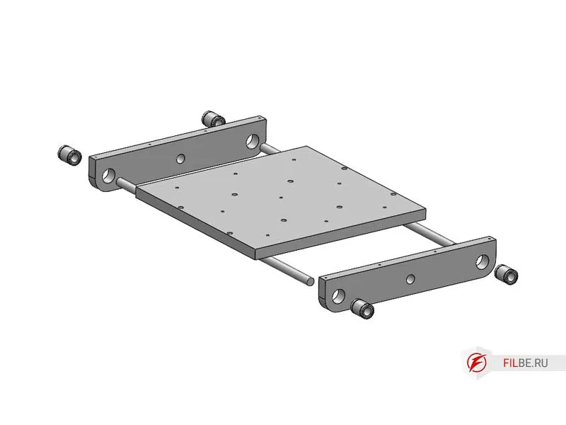
- X-Axis – carriage made of two parts: Table_Support and Table for mounting materials.
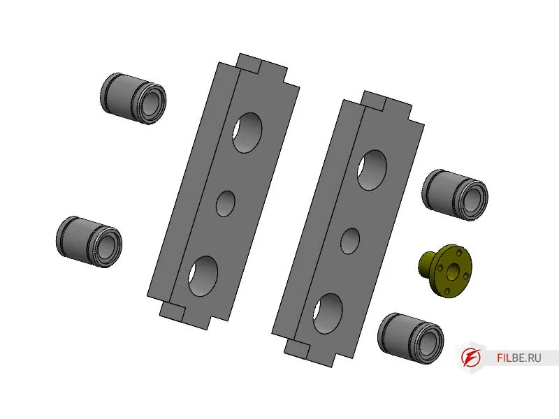
- Y-Axis – carriage consisting of: Post_Z, AxisZ_H, AxisZ_B, and Spacer_MZ, with pressed LM16 bearings in Post_Z.
- Z-Axis – uses the same components as the X and Y axes, with 12 mm cylindrical rails and a 10x2 brass nut.
Parts for the machine can be made by hand or purchased as a kit.
Materials and Components for the CNC Router from Plywood
-
Trapezoidal threaded screws:
- 12 mm, pitch 3 mm (X, Y axes) – 2 pcs.
- 10 mm, pitch 2 mm (Z axis) – 1 pc.
-
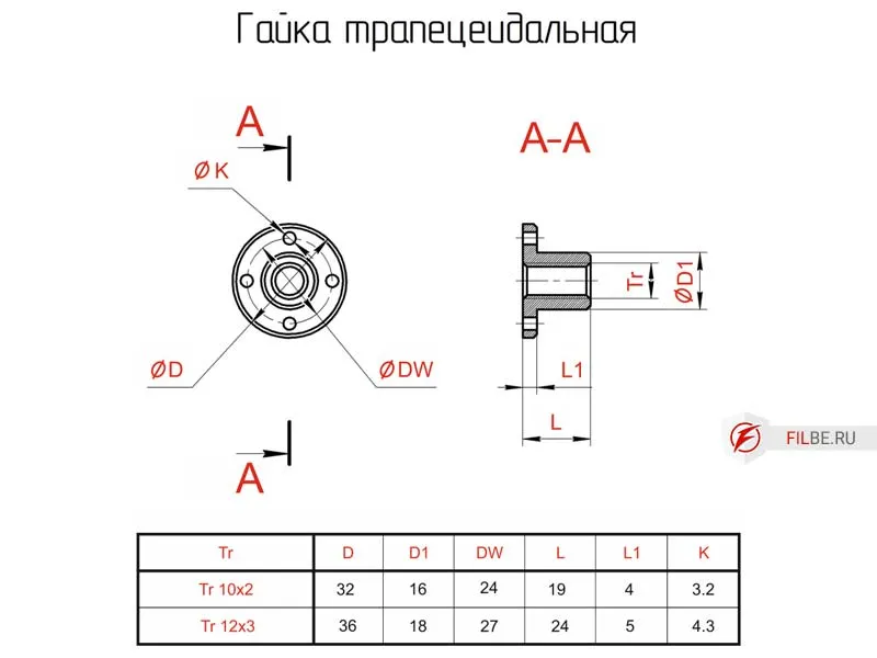
Trapezoidal nuts:
- 12x3 – 2 pcs.
- 10x2 – 1 pc.
-
Bearings 6027 (80027) – 3 pcs.
-
NEMA23 Stepper motors – 3 pcs.
-
Cylindrical rails SBR16 for the X, Y axes.
-
Polished shafts 16 mm diameter for X, Y axes.
-
Polished shafts 12 mm diameter for the Z axis.
-
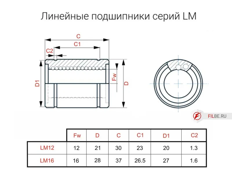
Linear bearings LM16 for the X, Y axes (8 pcs.) and LM12 for the Z axis (2 pcs.).
-
Laminated plywood (FSF), thickness 21 mm.
-
Wood screws.
-
Epoxy resin for gluing.
-
Spindle with a 52 mm diameter (300/500 W).
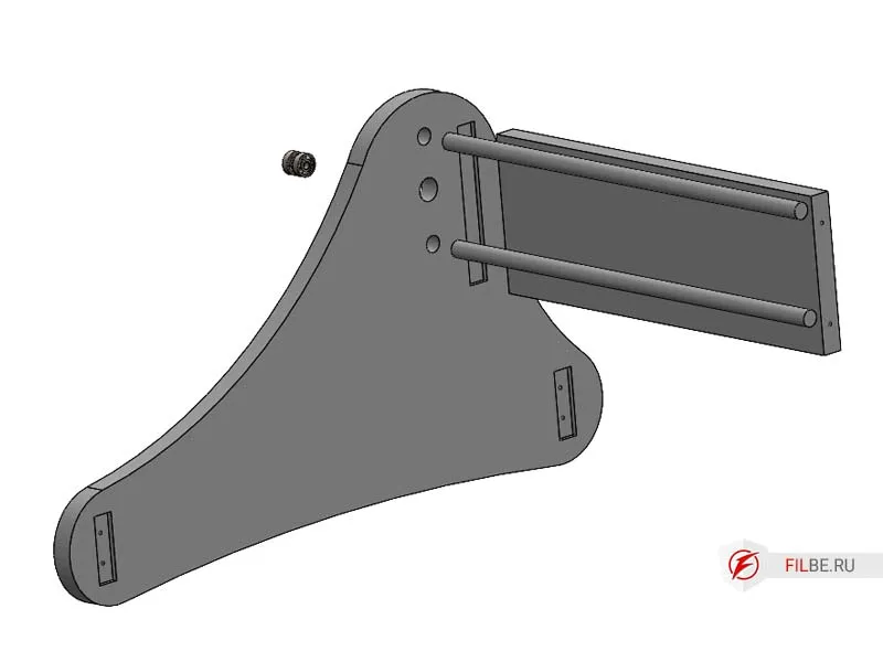
Component Drawings
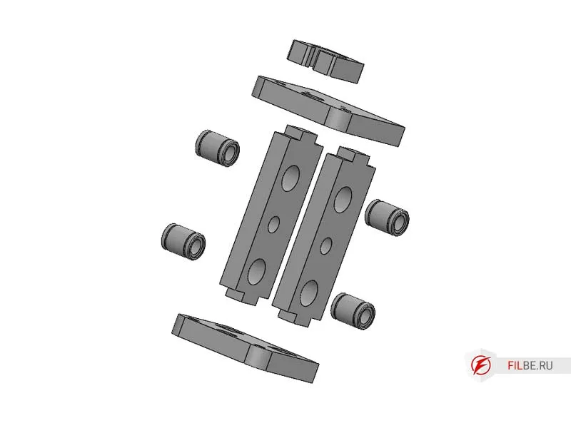
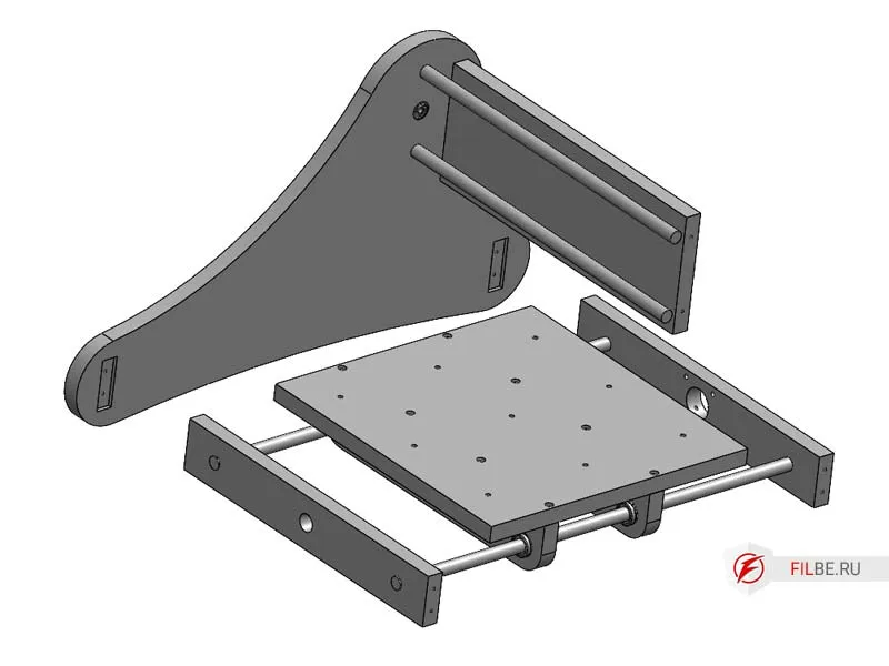
Exploded Views
All mating surfaces of the plywood parts are assembled with glue. It is recommended to glue the Table and Spacer at your discretion.
Assembly of the CNC Router Components
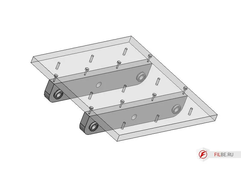
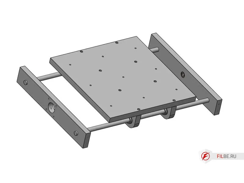
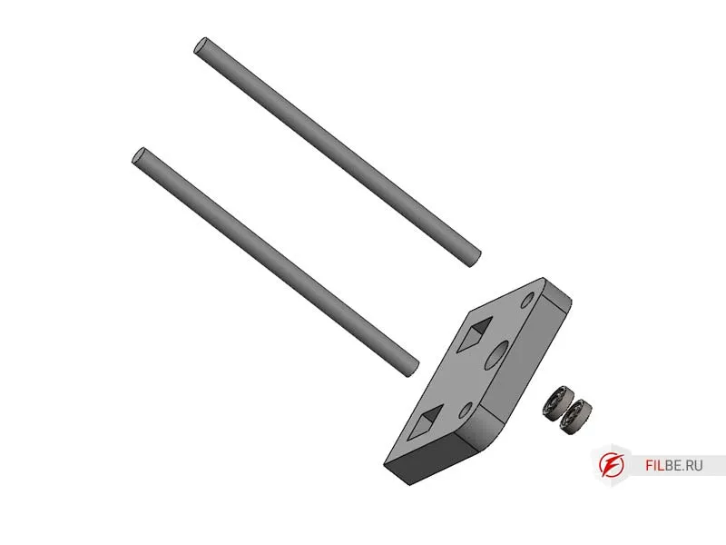
Assembling the Table
- Press the LM16 linear bearing into the Table_Support and install the trapezoidal nut Tr12 (pitch 3).
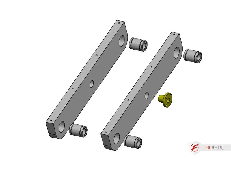
- Press radial bearings and 16 mm polished shafts into Support_P.
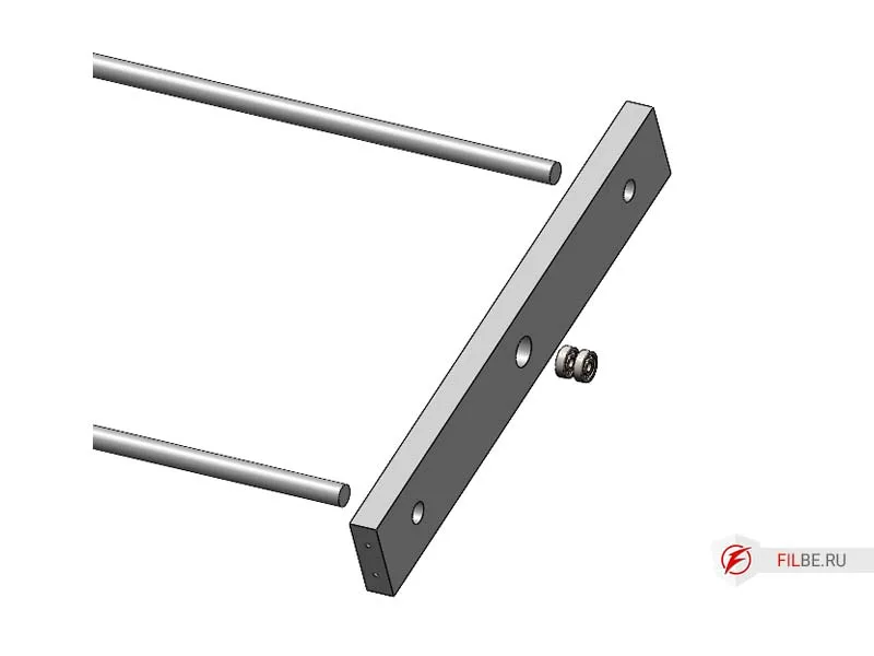
- Mount the Table_Support onto the polished X-axis shafts and install Support_M.
- Install the Table.
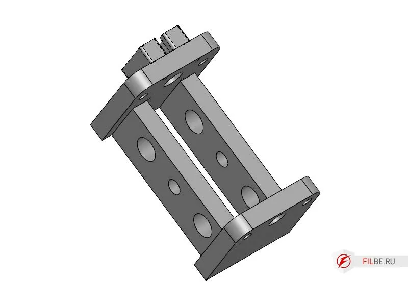
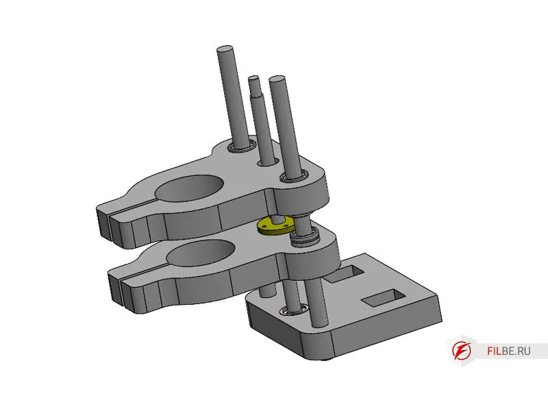
Assembling the Z-Axis
- Press LM16 linear bearings into Post_Z and install the trapezoidal nut Tr12 (pitch 3).
- Press LM12 linear bearings into the Clamp_52, install the trapezoidal nut Tr10 (pitch 2) into one of the clamps.
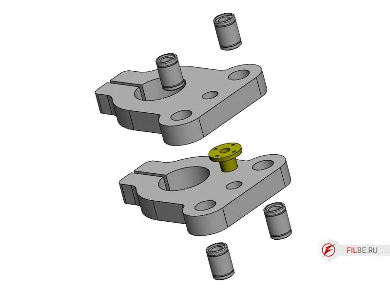
- Press radial bearings into AxisZ_H and install polished shafts.
- Install Clamp_52 onto the shafts, screw in the nut, and mount it in the bearings.
- Installing the Z Rack and Axis
Install Rack_Z into the corresponding part on AxisZ_L, then install AxisZ_U (Clamp together and allow the glue to dry)
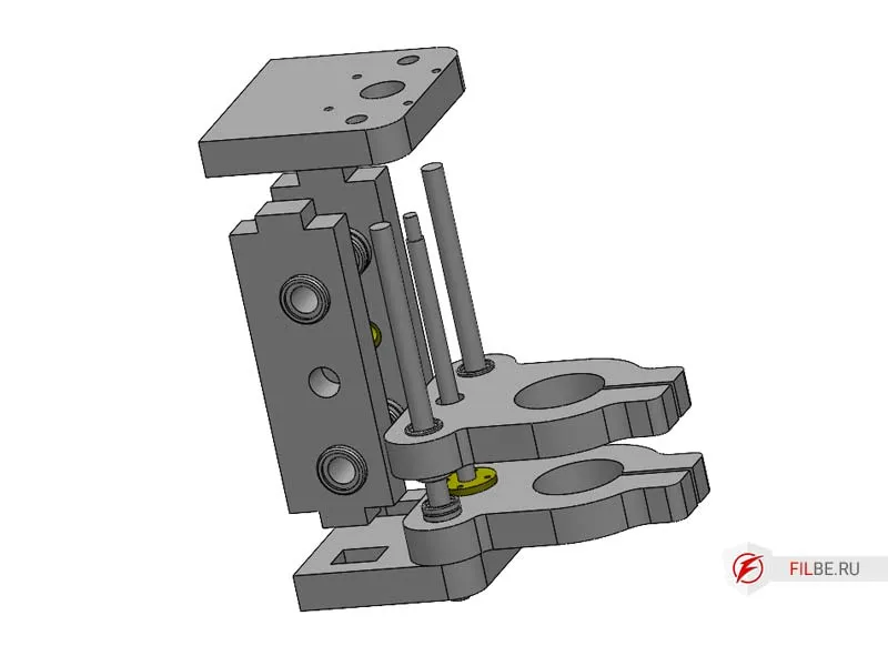
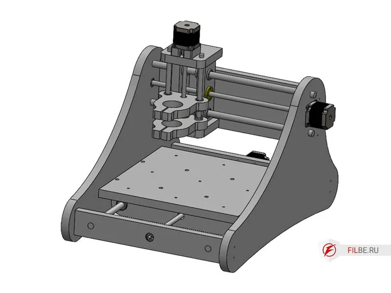
CNC Machine Assembly
- Press angular contact bearings and 16mm polished rods into Rack_R, then install Support_Y
- In the corresponding parts of Rack_R, install Support_F and Support_M, secure with screws
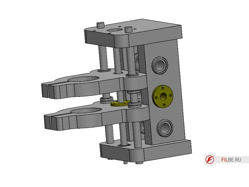
- Slide the Z Axis onto the rods and install the Frame, securing it with screws
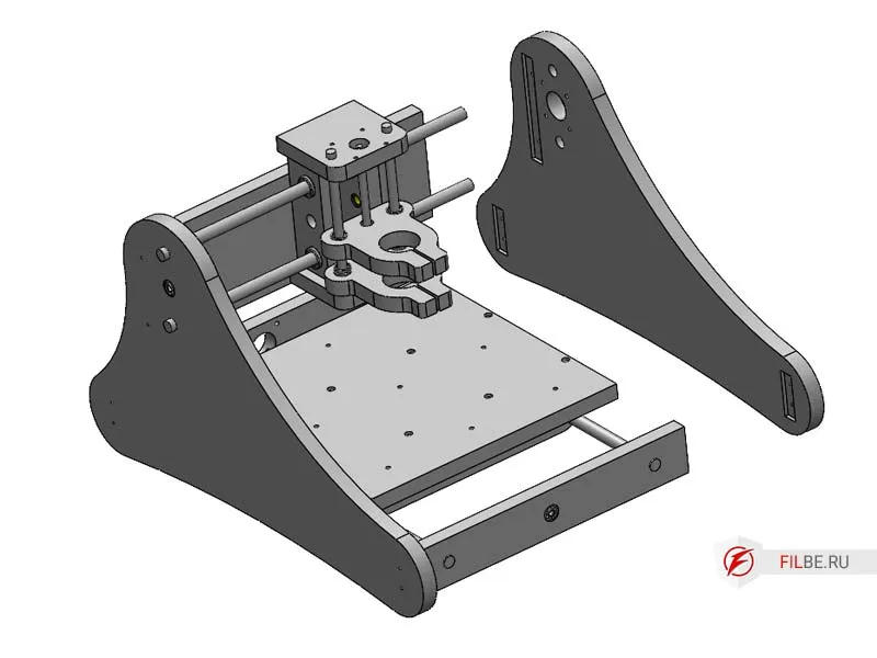
- Install Tr12 trapezoidal screws, attach motors to X and Y axes, eliminate backlash, and tighten the couplings
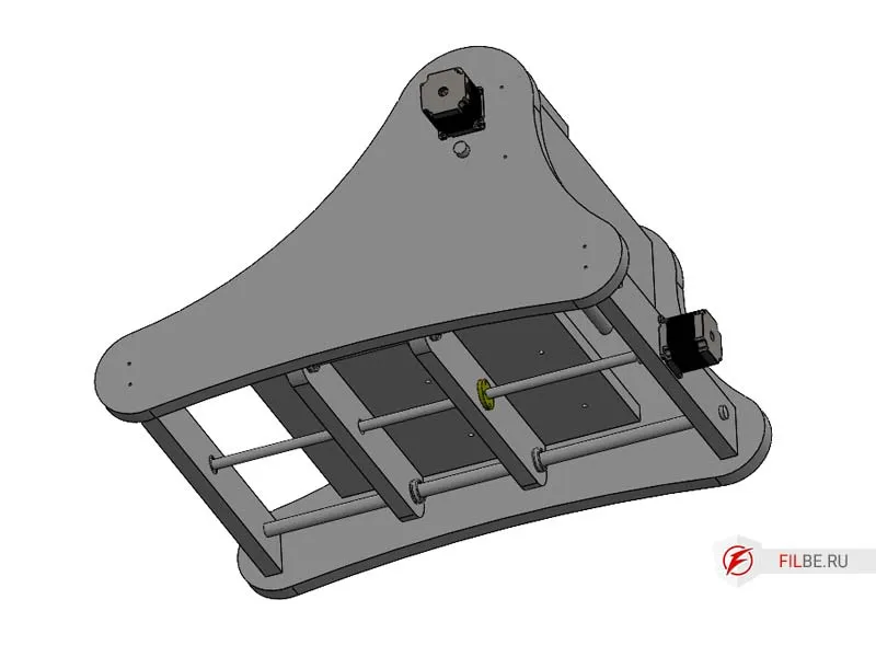
- Mount the Nema23 motor on the Z axis using a spacer to allow room for the coupling
The machine is fully assembled and ready for configuration
In the final article, I will describe the connection and setup of the electronics using ready-made components with the Mach3 software, which is suitable for both machines.
You can purchase the blueprints for DIY manufacturing here.